In order for the thread transmission to function, it is required that one part of the thread couple (and one of them only) is constrained from rotating so that the rotation of another part can be transferred into translational motion. In this case, it is the slider that is to be constrained to rotate.
The original design of the slider was to have straight rectangular splines milled on the outer surface, which would then couple with the keyways broached inside the housing. This would function perfectly in theory, and I still believe it would be the best solution to the problem. However, it was a pity that the department machine shop could not broach due to equipment limitations. Therefore, the design was altered in such a way that a sleeve with an opening was to be fitted onto the slider (which is an interference fit), and a screw driven into the slot to constrain radial movement.
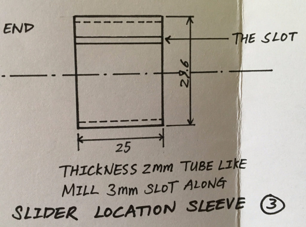
The drawing of the sleeve design is as featured.


I bought a section of black mild steel tube from the materials shop and turned both the inner and outer diameter to the nominal value. The black mild steel tube was horrible to turn, mainly because it was rolled and welded, which means the circularity is poor, and vibration is introduced every time the tool bit passes the weld (where the mechanical property of the material was quite different). Parting tools were not available for some reason, so the completed part was cut off with a saw and faced clean afterwards.
The design was altered on site and I did not manage to do the detailed calculations. Therefore, the first sleeve that I made was a bit too thick. After being fitted onto the slider, during which process the sleeve was expected to open up a bit, the diameter of the assembly was 0.3mm larger than the hole I had available. I could not force it in because it was supposed to slide inside a hole (which, on the contrary, required a bit of clearance, so even if I pressed in by machine, it will not function, and almost impossible to take out). Therefore, I had two options: either to bore out the hole in the housing by 0.5mm, or reduce the thickness of the sleeve.
I considered the first option seriously, and it sounded very feasible, except that it required a lot of messing around (clocking in the housing on a four-jaw chuck for example), and it would also make the cap too loose. The second option, however, was almost impossible, given the fact that the slot had already been cut, which meant I could no longer hold the sleeve in a lathe chuck.
The lab technician enlightened me by saying that I could make another sleeve, and bring it to the right thickness based on the measurements I have in hand. I did as he said, and it worked out well, except I still hate turning the black mild steel tube.
By making another sleeve, I can also correct the nominal sizes of the sleeve (basically by altering the position of the tolerance zone). This turned out to help a lot afterwards when I was summing up and remaking the drawings. This is a very vivid example of the importance of prototyping, as it is unlikely that some product could be designed very correctly in one go and require no further alternation.
In the next post, we can finally proceed to the housing. It has spanned a long time since exams are coming up, but I will manage to finish soon anyway. Thanks for reading.