Just realised I have not updated this series for quite a long time, so I will attempt to finish it once and for all today by talking a bit about the final touches on the housing. Machining of the shaped slots was covered in episode 3, so I will focus on the bore and the threaded holes on the wall in this post. Unfortunately, there will be no illustrative images.
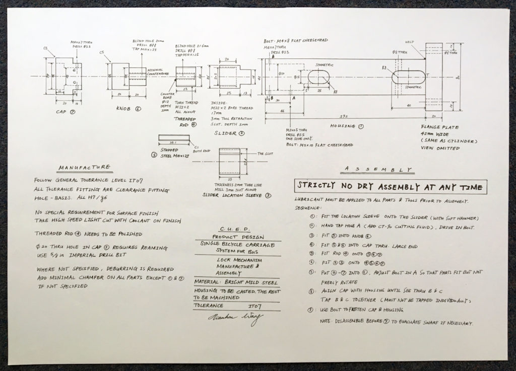
If you check the original design of the housing, a three-staged bore is required on the opening side of the housing in order to accommodate the assembly. However, as a result of altering the design, the complexity can be reduced to two stages. This does mean that more metal is to be machined away for the bore, but much better efficiency is achieved and better precision realised by this alternation, so it would be appropriate by calling this an improvement of the design.
The first stage of the bore is actually drilled and reamed. Since I already had the slot in place, it was possible to see through the slot whether the drill is through or not when the housing is spinning at high speed, which was very convenient, since drilling to a certain depth on a lathe has always been difficult, mainly because it is hard to find the origin (with head of the drill tapered and the tailstock moving freely when doing all sorts of adjustments). The hole was then reamed, which was a disaster. It was the first time I had ever done reaming, and as a result, I had been running the reamer in the reverse direction, running it seriously oversped, and without applying any cutting fluid. The hole turned out to be very messy, but I had no other way to recover the error but to bear with it and work on. The second stage of the bore was really straightforward.
After the bore was made, it was possible to fit the assembly into the housing and to check that the dimensions fit. The housing was then squared up in a milling machine vice and the screw holes drilled on the wall. These holes are really small in diameter, and, as a result, it was hard to find centre drills of the appropriate size. I was tempted to drill straight away without a centre, but held the thought and made centres anyway, considering it would be worse if those very slender drill bits spinning at 2500 RPM slipped a bit.
The last thing to be brought to attention is that I made a small mistake in the very final stage of assembly. The threaded holes on the housing and the cap were drilled separately, which was completely fine, but I tapped them separately as well, which caused the phase of the thread to not align. Therefore much difficulty was encountered when attempting to drive the screw into the holes, and I believe some cold forming happened when I did that for a few times because the operation eventually becomes easier, although the same thing may not work at all if larger in diameter. The tiny gap between the cap and the housing wall helped as well.
At this point, the product was finally finished and functional. The final work was weighted to be 2,470 grammes, which yielded a material utilisation rate of about 50%, considering that I donated several small pieces of unused steel to the shop. This is not a satisfactory number, mainly because much waste was induced by machining all the parts but not using other manufacturing methods. The biggest mistake was to decide to buy 45mm steel round bar and turn it down to 42mm, which wasted a lot of material, effort and money.
But hopefully, I can learn some good practice from that experience and help my design in the future. I do have an upcoming project of a larger scale in the summer, and I hope it will go well.