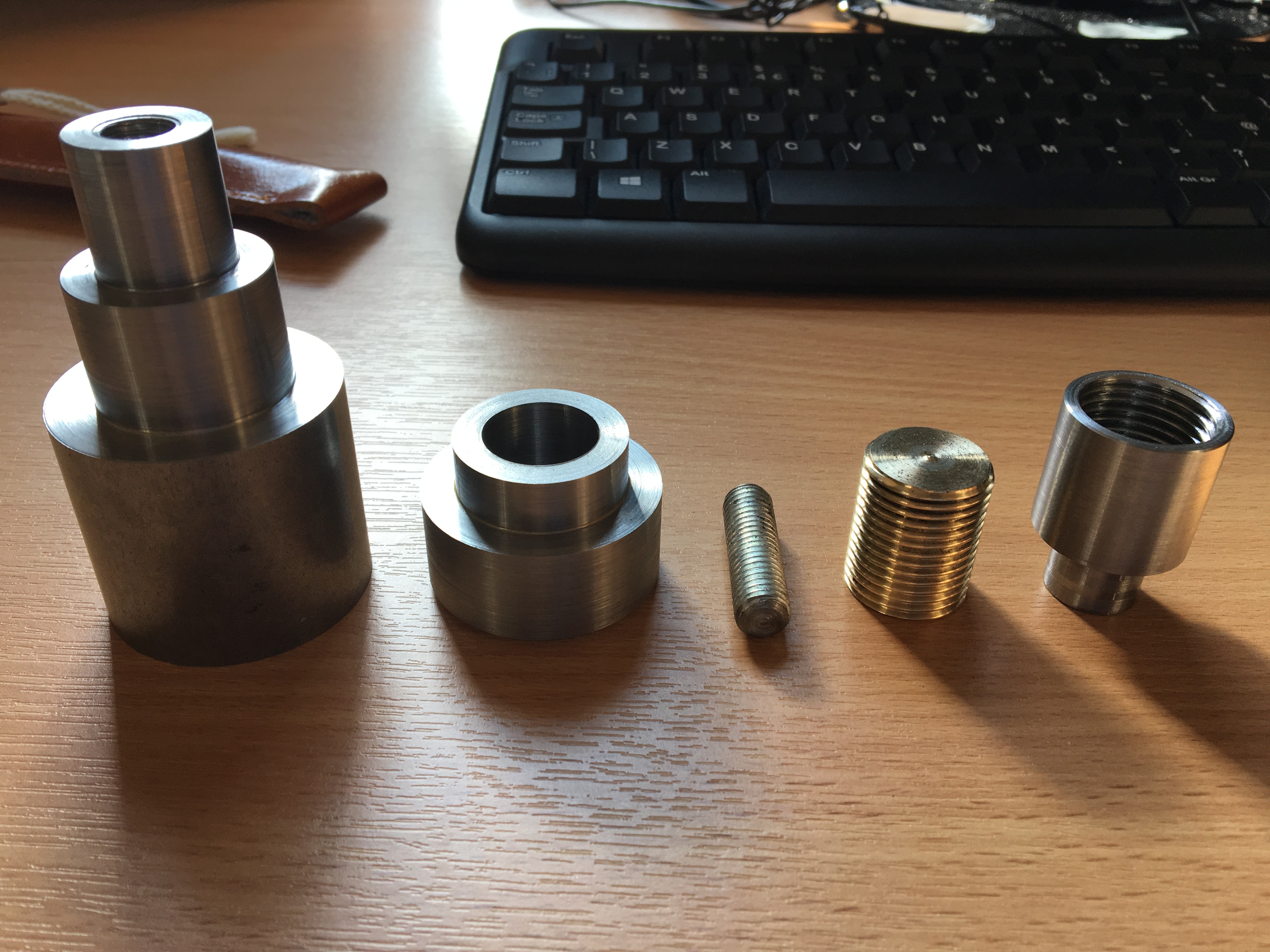
As promised, this article will be on the knob of the mechanism. Unfortunately, I do not have a photograph available of the completed knob, so please bear with the far left component in the image, which is a semi-product (after some alteration in design).
The knob was not originally designed to be a knob. The function of this part will be to lock and release the hook, which then secures and releases the bicycle. It is not desirable that anybody walking on the street can take the bicycle away when the bus is stationary and the owner, himself onboard the bus, unaware. Therefore, it is required that some measures to be taken to prevent unauthorised access to the bicycle carried.
Such design is common in daily life. If the manufacturer wants something to be really easily adjustable, good chances are they will design it so that can be adjusted by hand, for example, by using winged nuts. On the contrary, if something is designed to be not accessible for normal users, non-standard parts (or at least non-common parts) would be used, such as the screws on an iPhone, drivers of which is special, and, although purchasable, not a common household tool, or the piston assembly on a Montblanc fountain pen, disassembly of which requires special tools and will violate the warranty. Keys to the locks are very good demonstrations of this principle, which is exclusive to every lock sold. In my design, the threaded rod is to be turned by a special square-headed tool (quite like the chuck key of a lathe), so that unauthorised access may be prevented to some extent, given that when somebody is using the bicycle carrier, the tool shall be in his possession. However, in order to save time during the prototyping process (and it would be unlikely for a tool and the specially shaped pocket not to work together), a knob was used instead.
Turning the knob is fairly straightforward, but there are several notable problems that are worth addressing. The first one is the manufacturing process. The knob was turned out of a 45mm steel round bar, which was fairly short, and after the turning was finished, the knob was to be cut off the piece of raw material with a saw. However, for the saw to be used, the workpiece must have sufficient length to be gripped in the vice securely. This was not the case in my work, and it took some considerable effort to do it (requires another piece of material of exactly the same thickness to balance the vice). A modification to the process may be made so that the knob be parted on a lathe with a parting tool, which is much easier.
Another design error was the outline of the knob. Initially, it was three stage, with the last stage of a diameter 10mm and threaded. It took me considerable effort to turn 45mm raw material down to 10mm (and wasted a lot of metal and money), only to find out that threading it with a die destroyed the accuracy completely, and the knob did not run coaxially with the threaded rod after assembly. The last stage was got rid of, and a threaded hole with diameter 10mm was made. Then, a small piece of studded steel was used to fasten the two pieces, which worked well. Problems with this design being that sometimes the assembly loosens up by itself, and it may be a better idea to apply some adhesive into the threaded holes, at least one side of it, to make the studded steel stay in place permanently.
I suddenly recall that I have missed a part, which is the location sleeve on the slider. I will briefly discuss that sleeve in the next post, and hopefully we can proceed to the bore in the housing and the final assembly after that. Thanks for reading.