It has been a week since I last wrote about the prototype since I have been working on obtaining my UK driving licence. However, I just messed up my practical test, and therefore now I have time to continue this series. I hope I can get these posts done before the Tripos slam down onto me, else I will probably forget some of the details when I pick it up again.
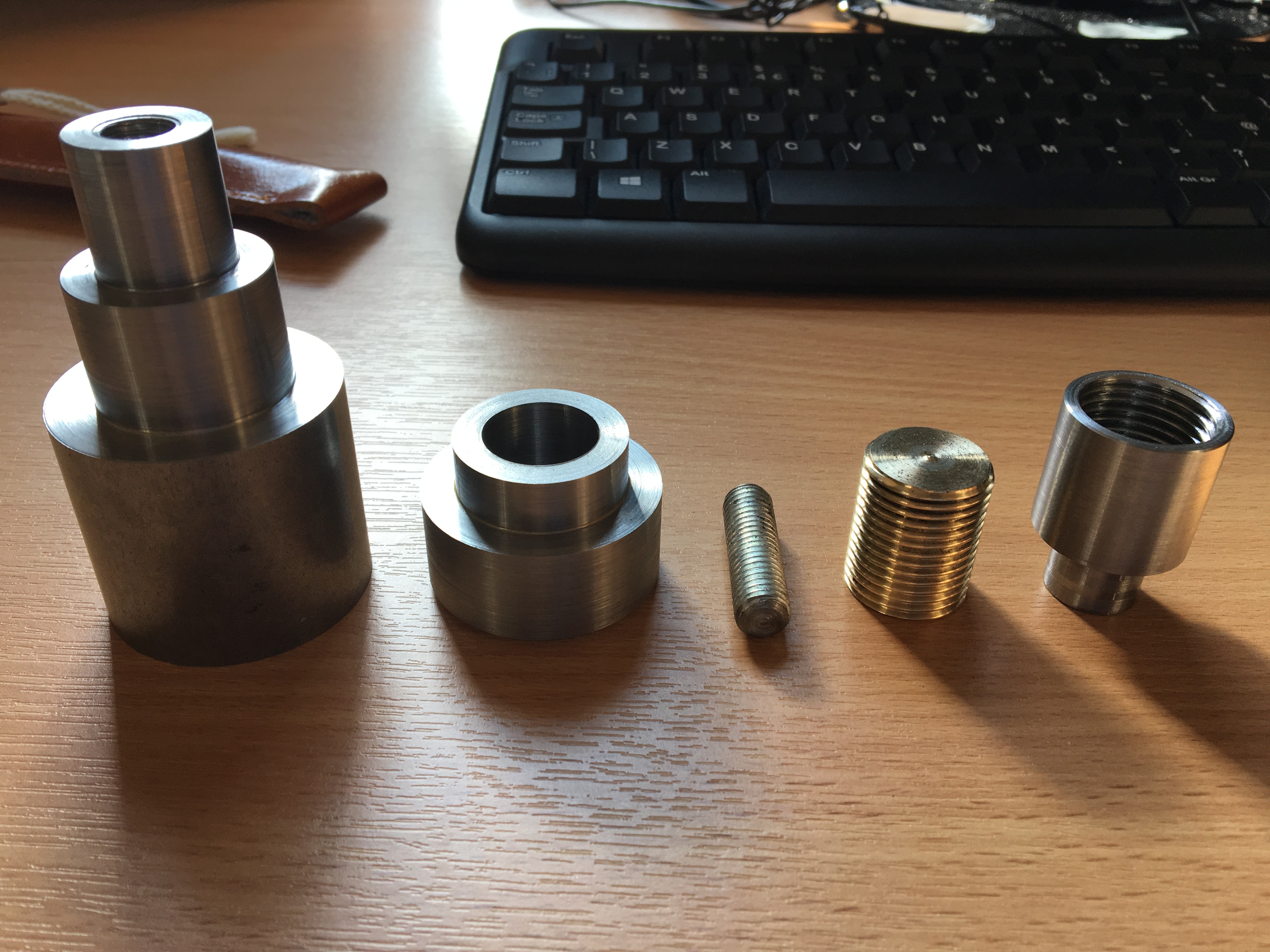
This article, as promised, is on the making of the threaded rod, which is the second component from the right in the image. Weirdly, this is the only brass component in this piece of work, and I would like to start from the material first.
I must admit I did not design this component to be brass for a purpose. However, when I bought the raw material for manufacture, in order to save some money, all the steel rods I bought was 45mm in diameter (so that I save some weight on the extra bit that goes into the chuck). However, I soon realised that turning everything out of 45mm rods (especially the smaller parts, where I have to take about 20mm of the diameter off) was a terrible idea, extremely inefficient and wasting a lot of material. Therefore, I looked for a piece of material that had a diameter close to the threaded rod (20mm) so that I could save some turning, and, in order to save money again, from the trash bin. The piece of brass was what I found.
After I decided to use that brass to make the threaded rod for my work, I realised that there were certain advantages of using it. Brass has unparalleled machinability, very easy to turn, to saw, and to deburr and make minor adjustments by hand if necessary. Besides, brass is a self-lubricating material, which might result in it to run better inside the mechanism.
The raw material whose diameter was 20.5mm (might be some better values in Imperial), was turned down to 20mm, and a deep groove was cut, in order to retract the tool at the end of the threading operation. Since I already had the slider in place, the thread was pretty much turned by trial, i. e. when it came to a finish, I made light cuts and just to the point when the two components fit. The threaded rod was then drilled on one end, which was going to be made into a threaded blind hole.
However, after I took the threaded rod off the machine, the thread stopped working. In order to fit the thread, some minor trimming on the inside of the slider was conducted. The threaded rod was then polished. The last thing to make the thread run smoothly was to apply some lubricant to the thread couple, and in my case, some pencil.
Graphite, as a lubricant, can be very messy sometimes, so I changed the lubricant into tapping fluid later on (which was the only mineral oil handy). However, I should have made some specifications on what type of oil is to be used for the mechanism. It should be able to run dry in theory, but it never worked so.
The next post will be on the knob, which is a part originally so poorly designed that it took me a lot of time to machine and never worked until I changed the design. I hope it could be interesting.