Making the cap has been a pretty straightforward process, but to begin, it had something to do with the housing, and that is the reason why I chose to schedule this post here.
The housing, after the slots and a 16mm through hole (which I will come back later), was overlength. The reason for that was when I cut the raw material, I had to leave some length so that the part could be held in a chuck when it is being turned. Therefore, I had about 50mm extra length on the circular end of the housing, with a 16mm through hole inside it that would otherwise go to waste if I made no use out of it.
I chose to cut that extra piece off, and make the cap out of it, mainly because there is already a hole inside, based on which I could bore, and it was turned down to size together with the housing itself so that I did not have to do anything more about the outer diameter.
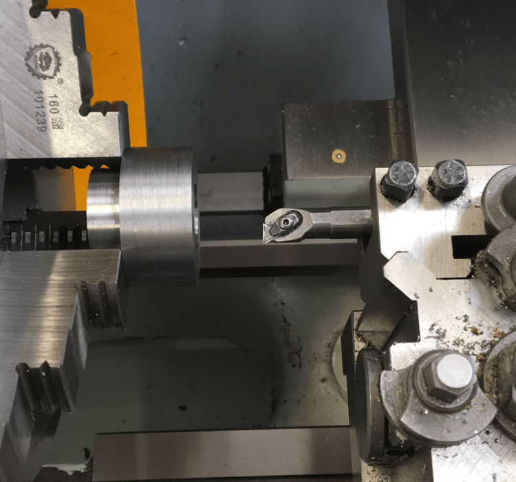
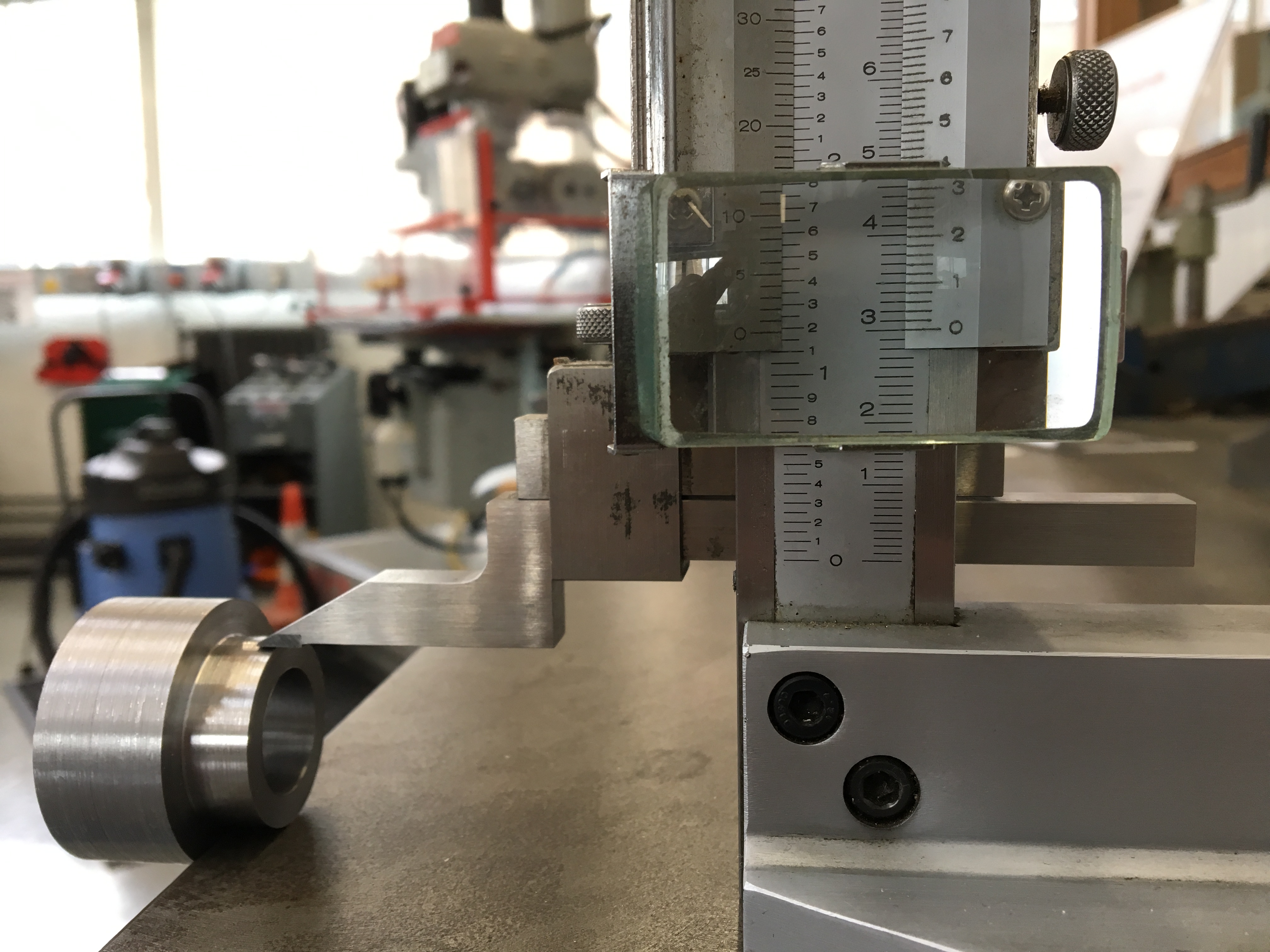
The extra piece was cut off on a saw bench and machined to length.After that, a neck was turned, all very basic lathe operations. The neck was required to be several dozens of microns smaller than the nominal diameter so that a clearance fitting could be achieved. However, I just turned it down to the nominal size, just in case the housing was bored larger than expected. It is easier to correct a larger cylinder from the outside than correcting a larger hole from the inside, which is not generally possible.
The 16mm hole was bored to 19.8mm and reamed to 20mm. Reamed surface was very satisfactory. One end of that hole is to be bored to 30mm. I thought about reaming it again, but the counter bore was so shallow that the taper of the reamer could be accommodated, so it would not work. In order to get a smooth surface on the interior, I took a light high-speed finishing cut and flooded the hole with coolant.
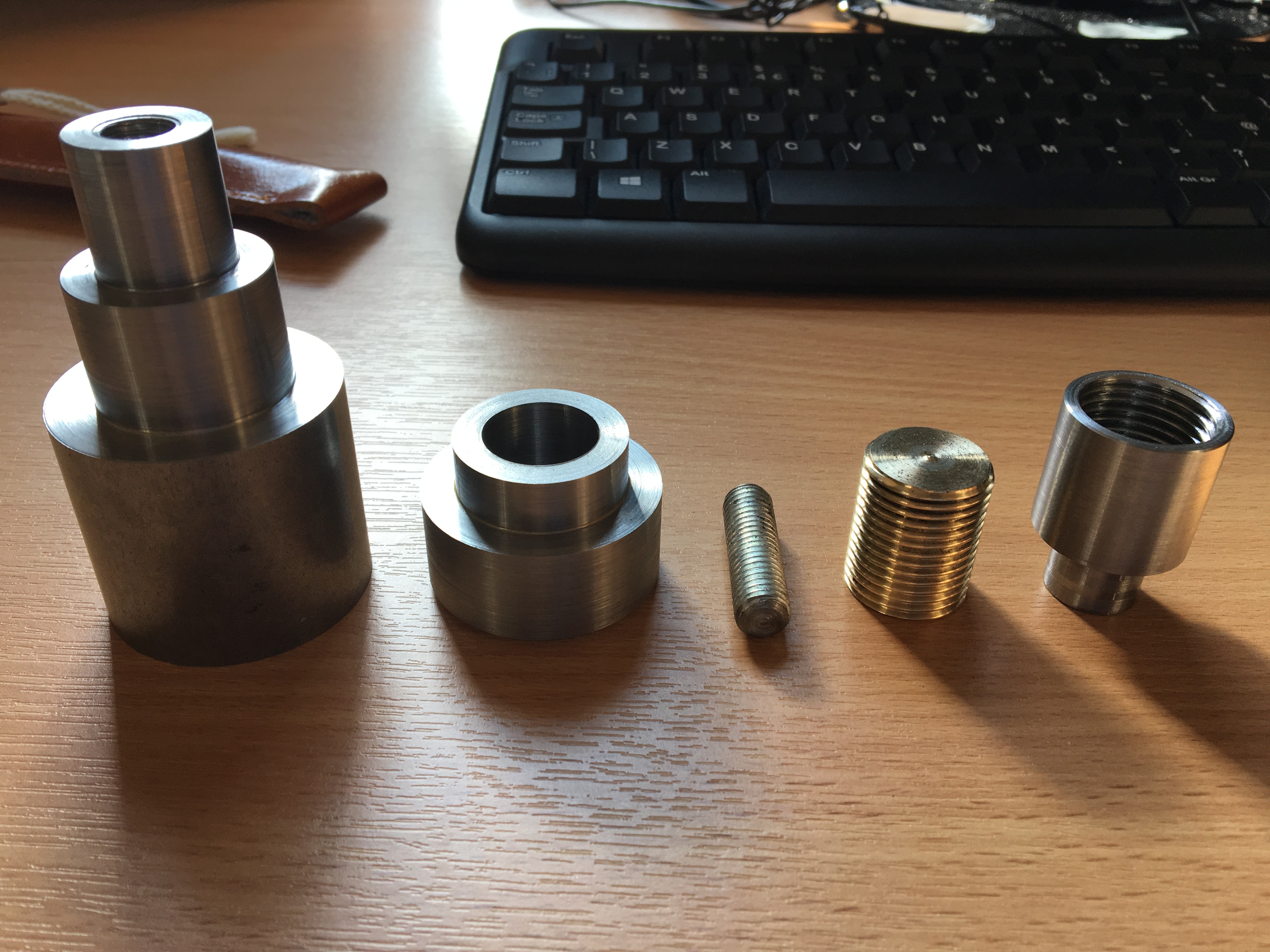
After that, minimal chamfer was added everywhere, and a 5mm chamfer on the side that will actually face the operator. This was a fairly easy part to make. In the picture below, the completed cap is the second component from the left.
In the next article, I plan to write about the threaded rod, which is, weirdly, the only copper part inside this piece of design (second from right). Thanks for reading.