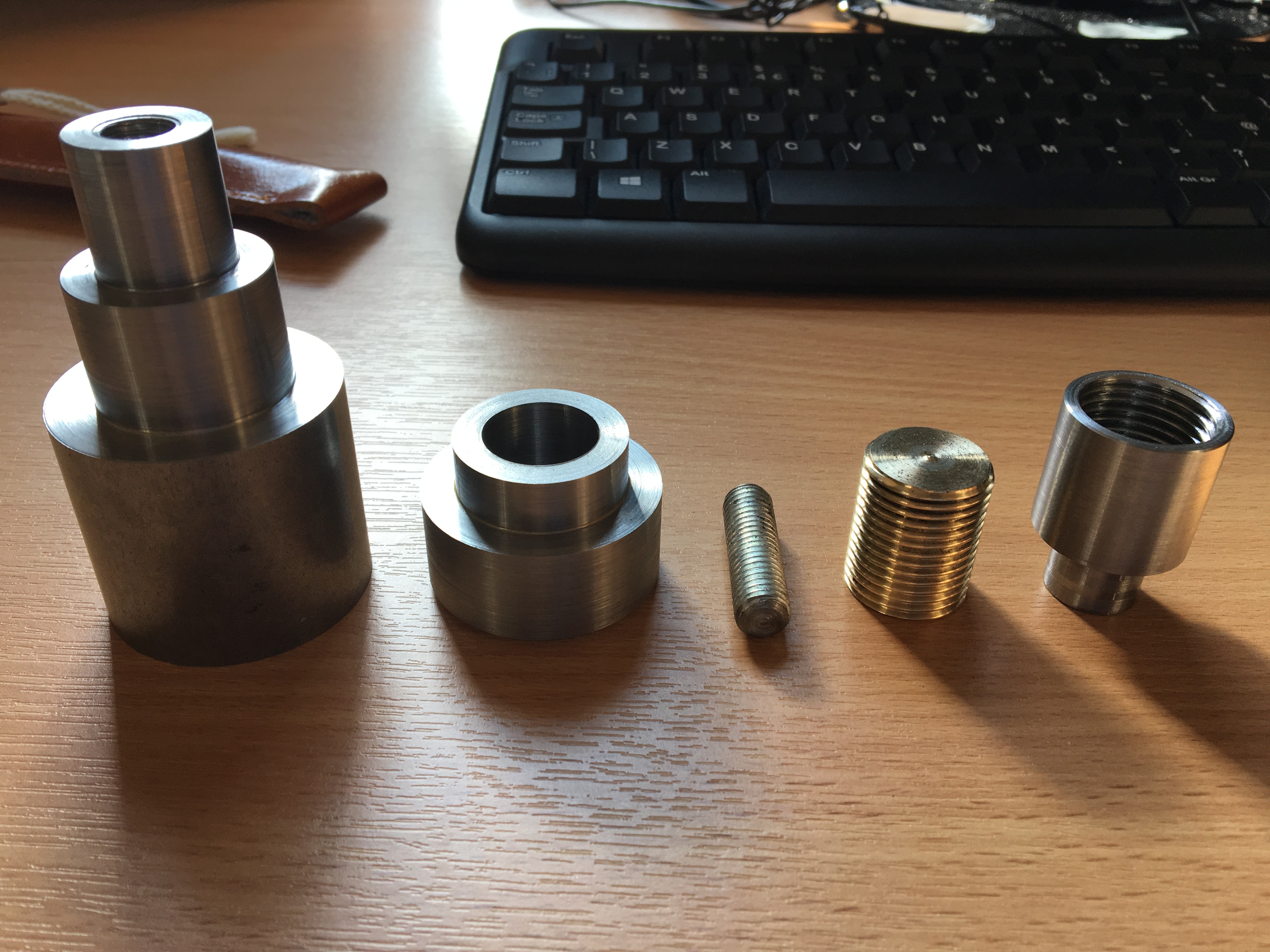
The slider, whose purpose is to slide inside the housing under the driving force provided by the threaded rod and, therefore, to lock and unlock the hook, is the first component in the above image from the right. This is a circular, tube-like component which contains thread on the interior of a blind hole. This part turned out to be very troublesome to make.
The basic outline of the slider was turned out of a piece of steel bar. It was cut off by a parting tool on a lathe afterwards, and the face on which the big blind hole will be drilled was machined clean, and centre drilled.
The original design of the thread on the interior demanded M22*2.5 thread whose minor diameter is 19.5mm. Therefore, a 19.5mm drill bit was used to create the blind hole. It turned out to be impractical to control precisely the depth of a hole by turning the handwheel on the tailstock, given there was no way to find a datum. The hole was created to have approximately a depth of 20mm.
Diameter of the hole was measured and it turned out that the blind hole was about 20mm in diameter, which is larger than the nominal diameter of the drill bit, but also to be expected, given the amount of swarf building up inside the hole, rubbing against the wall, and the vibration of the machine. The depth of the hole was about 19.5mm, leaving a bit of clearance for me to bore it to precisely 20mm.
The taper at the end of the blind hole, as a consequence of drilling, must be removed. Therefore, the end of the hole was bored flat and to size. This was not a very easy operation, given that I was not able to see a thing inside the hole, and I had to machine in several steps, to avoid overloading the cutter. The boring bar was quite a small one so great care must be taken so that significant vibration was not induced, which may ruin the precision.


M22*2.5 tap and die set was found in the tool store, and attempts were made to manually tap the blind hole. However, given the shallow depth of the blind hole, the tapered tap could go all the way in without actually cutting, and, as a result, I could only start with a second tap. That was proven to be extremely difficult as a lot of force was involved in the tapping operation, and there was no practical way to hold the slider piece securely. I tried to hold it in the three-jaw lathe chuck, but with no success, and the relative movement between the slider and the jaws damaged the surface very badly.


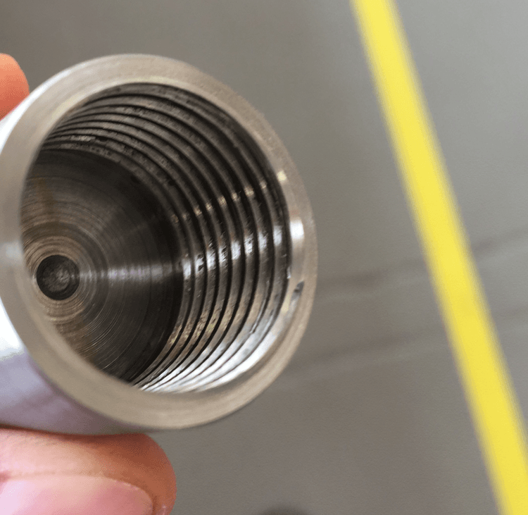
Therefore, I had to bore the threads on a lathe. The largest form tool I had available allowed me to bore a maximum pitch of 2mm, so the design had to be changed to M22*2. Before the threading operation, a groove at the end of the blind hole, with a depth of 1mm, was bored and used as a retraction slot for the boring bar during the threading operation. The width of the groove was determined by the width of boring bar tip, which was 3mm. This meant that I could run the machine up to 17mm of depth, and turn the chuck by hand to anywhere 18 or 19 (I chose 19), and retract the tool and withdraw the boring bar. The thread was bored in this way.
In the next post, I will write a bit about the threaded rod, which was built to fit the slider. I know I promised that this post would be on the threaded rod, but just to follow logically the sequence of my work I adjusted it last minute. Apologies for that.