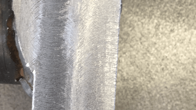
After the flange was welded onto the bar, the flange was brought to size on the milling machine. This was a very painstaking process, as when the flange was not to size, it could not be gripped in the vice, and by gripping the part by the bar only, the part needs to be clocked in every time. However, the flange was not brought to size beforehand in order to leave some space for welding (approximately 2mm each side), and the weld was faced off a bit afterwards as well. This is clearly visible in the image.
After the flange was brought to size, i. e. the part now sits on a flat surface by itself, milling became rather straightforward. The two through slots were first made. In order to cut the 16mm diameter on the ends, a 16mm end mill was used. However, it was not particularly good at drilling, and 16mm slot mills were not available. Therefore, an incremental method was used to create the holes. The part was centre drilled, then drilled to 8mm diameter. The holes were then enlarged to 14mm diameter with a drill. After that, the end mill could go all the way in, as the centre part with no cutting edges was avoided.
After the mill was fully inserted, the length was fed in the X axis. This was a very heavy cut. I attempted to use the CNC method first, by taking incremental light cuts, but this took a decade by hand and overshooting often happened. Therefore, I decided to cut it in one go. The worst part of this operation was that coolant was not available on the milling machine I had been using.
In order not to drill into the vice, a part of sacrificial material shall be placed underneath the part. Ideally, it should be a piece of aluminium alloy, but I could not find a piece of aluminium of proper size, so a piece of wood was cut instead. The good thing about using wood is that a lot of noise will be made when drilling into it so that I realise that I am through at the first instance.
However, using a piece of wood underneath created lots of problems as well. The most severe one was that there was no place to evacuate swarf. Therefore, I had to retract the mill every now and then and get rid of swarf inside the hole, initially by finger, and as the cut went deeper and swarf got hotter, by whatever a stick I could find (mostly the 8mm drill). The best thing I could have done was to find a piece of magnet to get rid of swarf or use a blower like a hairdresser. However, neither was available then. Swarf that accumulated inside the hole also damaged the surface very badly.
I should have completed both slots in one go, therefore only need to square the part up once. However, as I completed the first slot, the workshop was about to close, so I did the hinge pin hole instead. That hole was pretty straightforward.
The second slot was made in a similar manner, but this time, as the slot was shorter, the two drilled holes overlapped, and I experienced the drawbacks of drilling half a hole for the first time: the drill wobbled very badly and the hole turned out to be off by a lot. Again, a better thing I could have done is to drill one hole and take a heavy milling cut all the way to the desired length.
The next part on the housing will be how the bore on the other end was made, however, this was, in fact, the last thing I did, because the housing was the part whose length was to be adjusted at the end to fit the other parts. Therefore, the next article will be on the cap, and the bore on the housing has to wait until the last article, just to follow the sequence through which I worked. Thanks for reading.