The housing is the largest, heaviest, and most complicated part to make in this prototype. Therefore, I am going to spend several posts on documenting the process of making the housing.
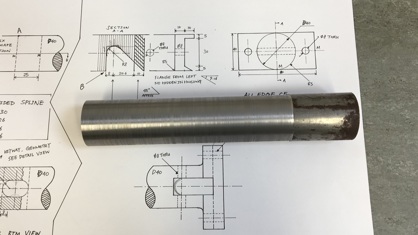
The original design required the diameter of the housing’s circular part to be 40mm, however, the surface of the 40mm bright mild steel round bar that was available in the store was horribly bad (just like the right part of the round steel bar in the first picture). Therefore, to make use of those steel bars, some machining or grinding must be applied, resulting in the diameter to be smaller than the nominal one. Although this should have brought no problem (and it turned out that I should have gone for the 40mm bars), the 45mm round steel bars were chosen. Two pieces of such bars were bought, with a gross weight of 5.3kg and price of 13.2GBP.
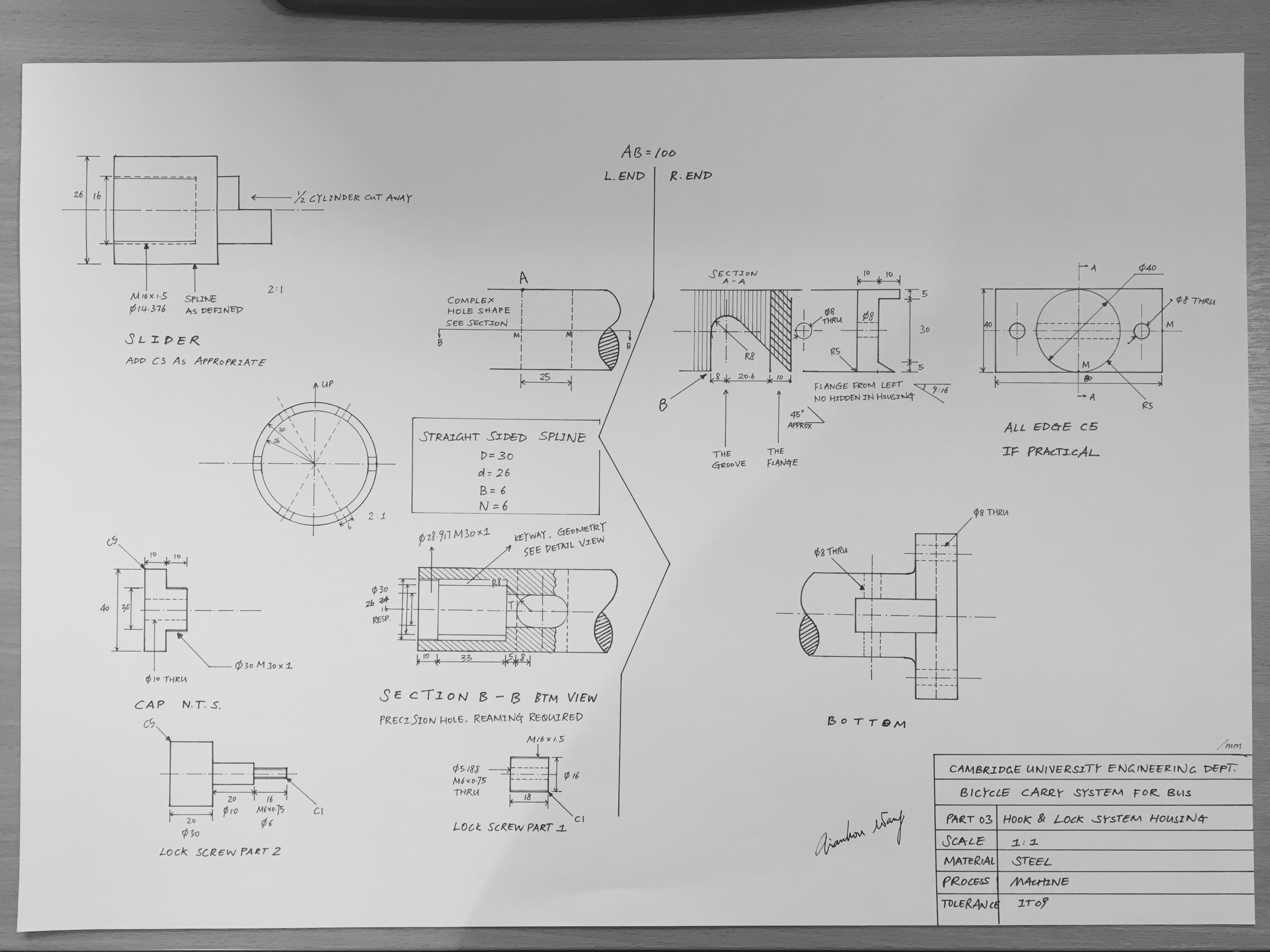
A flange was involved in the housing, and according to the original drawing (which has been updated after the prototype was completed), dimensions of the flange should be 80*40*20. Therefore, a piece of bright mild steel flat bar, with weight 300g and price 1.3GBP was bought.
Both the steel bars and the flat bar was cut from a larger piece of raw material with a saw, and that resulted in a terrible surface finish and a significant amount of burs. Therefore, the round bars were faced on a lathe and centre drilled on both sides. The flat bar was faced on a milling machine.
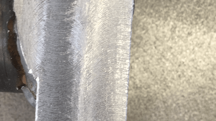
The next job being done was to turn the round bar down to a diameter of 40mm. The cutter experienced problems and the cut did not go well, resulting in a rough surface finish, which is present on the final product. The surface should have been ground before further work was conducted. It was found that to turn down a diameter of 5mm on such long bars was very time-consuming, so the design was changed so that the diameter of the housing was set to 42mm, resulting in less work. The round bar was flipped in the lathe in order to turn its entire length down to 42mm, and it was found that the two ends were not very coaxial. Reason being the three jaw chuck being used was not very accurate, and there is no guarantee that the bar was originally perfectly round (which is highly unlikely the case) when it was first gripped in a chuck.
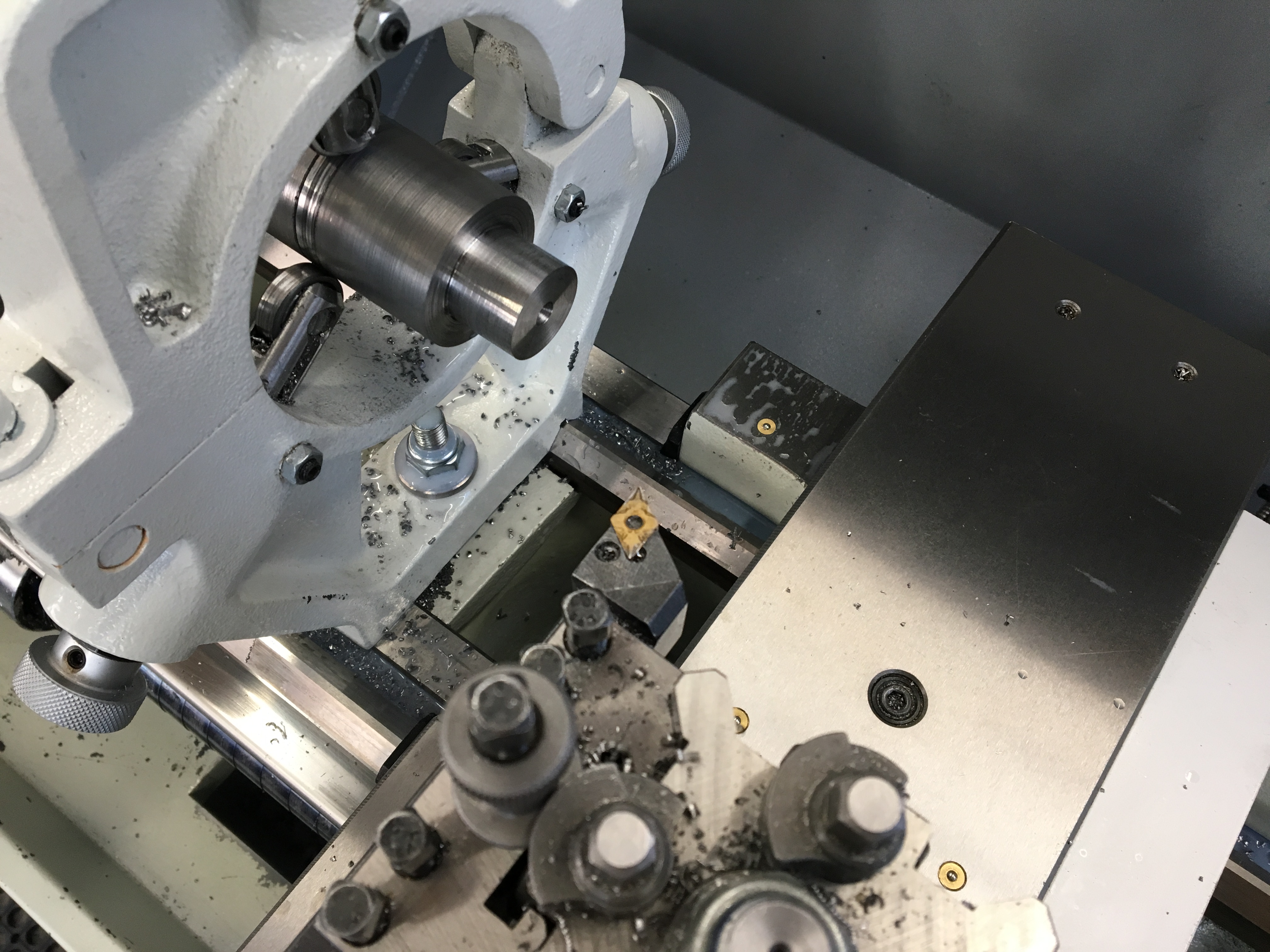
The flange was to be welded onto the bar, and in order to centre the parts and make sure they stay intact and square during welding, An interference fitting was designed. The end of the bar was turned down (with the assistance of a fixed steady) to 16.2mm for a length of 20mm (the thickness of the flange), and a 16mm hole was drilled in the centre of the flange. The drilling process was quite rough, and there was very serious vibration. After the drilling finished, the hole was measured, and it was slightly tapered. This was not normally desired, but in this case, it might help, as the taper served as a lead to the press. A small chamfer was added to the end of the bar, to lead the press and also to provide space for welding.
After the parts were machined, an oil press was used to push-fit the bar and the flange plate. Welding was then conducted. After the parts were welded together, the flange was machined to size. The surface, however, was not very good, though I have tried to take high-speed light cuts. A lot of burs were created, and minimal chamfer was added by hand during the deburring process.
In the next part of the housing, I will explain how the slots, holes and threads were made in the housing. Thanks for reading.