The SOLIDWORKS Flow Simulation is an add-in to the famous middle-of-the-way 3D modelling software package SOLIDWORKS. It offers the basic CFD functions within SOLIDWORKS i.e. no need to go to another programme. This add-in is straightforward to use, as this article would intend to show. This post illustrates a test project using the Flow Simulation add-in, showing its basic operational procedures and analysis capabilities.
This is part 1 of the post, and this post is dedicated to the construction of the simulation project, including modelling, setting-up the wizard, and adding boundary conditions and goals.
It should be noted that, since this project is for experimental purpose, the meshing is automatic and very coarse. The entire model contains just above 5000 cells with over 3000 contacting the wall. This is insufficient to produce results of meaningful accuracy, but helps to control the solving time down to the order of several minutes.
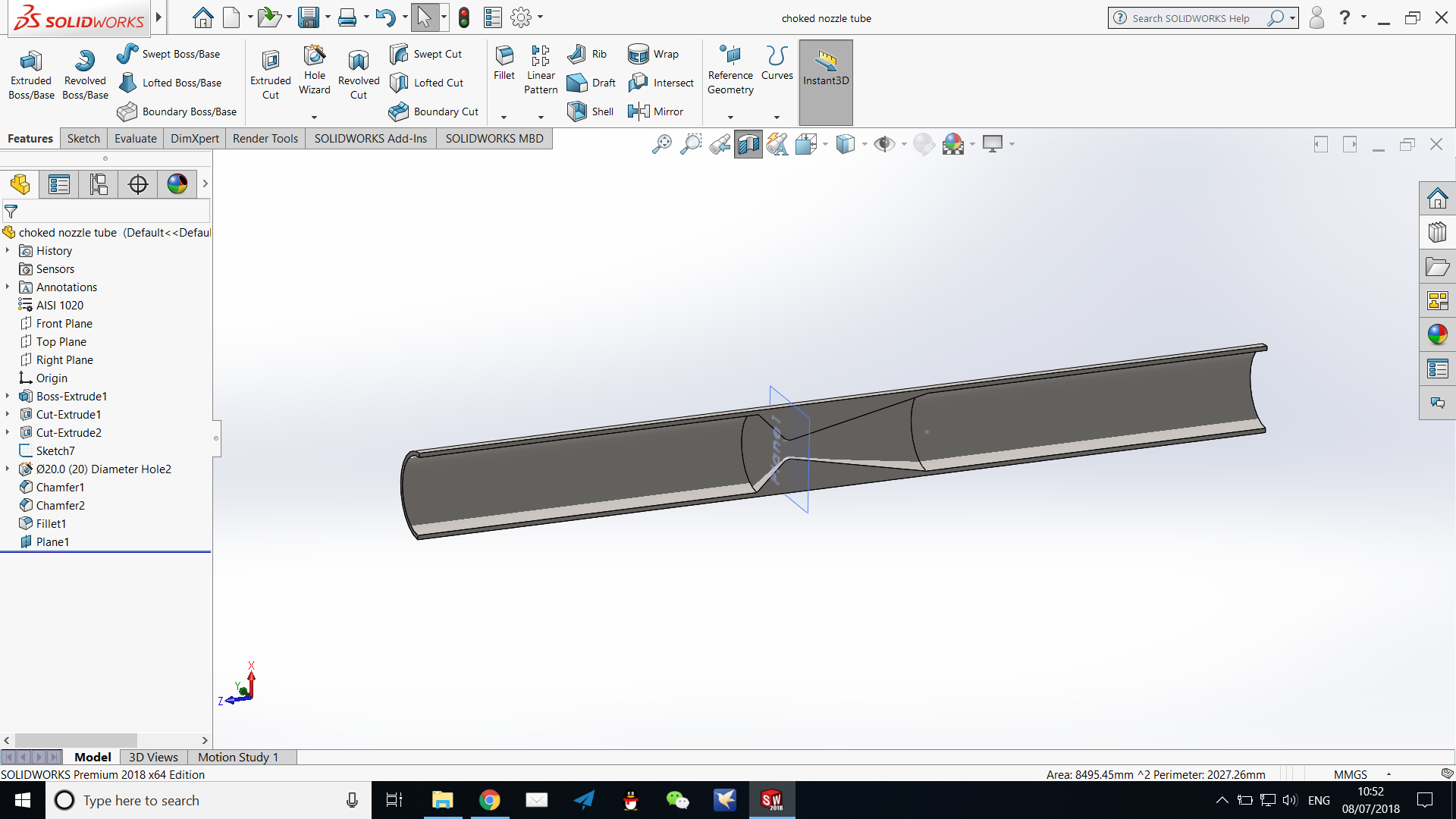
Model of the choked nozzle tube, in sectional view
This model features a choked nozzle section with inlet from the left and exhaust to the right. It also has long sections of uniform channel to uniform the flow.
The flow motion study can be set up after the solid model is complete, however, it should be noted that you may need to modify the model slightly should problems be encountered during the solving process. In this case, I have attempted a 35mm chamfer on a step of 35mm, and the resultant feature does not contain an edge that SOLIDWORKS would recognise as a human being. This led to singularities in the solution and the Mach Number burst to over 200, which can be clearly identified as incorrect by those with knowledge of the boundary conditions and some fluid mechanics. Therefore, the model has to be adjusted slightly. Infinitely thin sections, small gaps left in the model (particularly sheet metal model), may contribute to such problems.
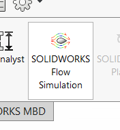
We first turn on the flow simulation add-in.
Click on this icon to turn on the flow simulation add-in.
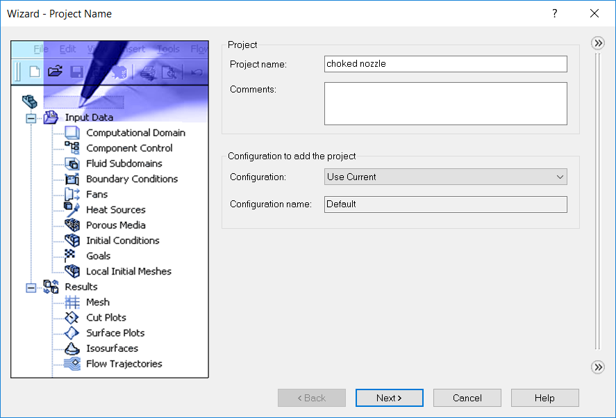
Start the wizard to name the project.
The Wizard is a user-friendly interface provided to guide the user through the set-up phase of the simulation project. The wizard is to be used in this project.
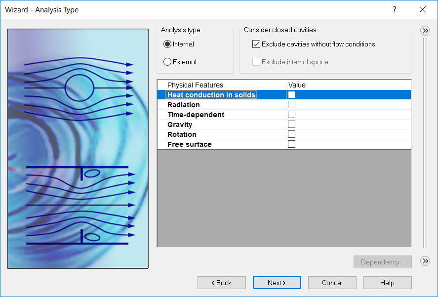
The analysis type must be specified. As illustrated perfectly in the wizard, there are two types of analysis supported in SOLIDWORKS flow simulation, namely internal analysis, and external analysis. We use internal analysis in this simulation because the flow within the choked nozzle tube is to be studied. There are physical features to be considered in each analysis project. In this choked nozzle analysis we are concerned with none of these (we ignore the effect of heat transfer, look for a steady state solution, and the effect of gravity can be neglected since we are concerned with the flow of air under high Mach Numbers, etc.). However, these can be conveniently set up if the scenario deems it necessary.
Set up analysis type.
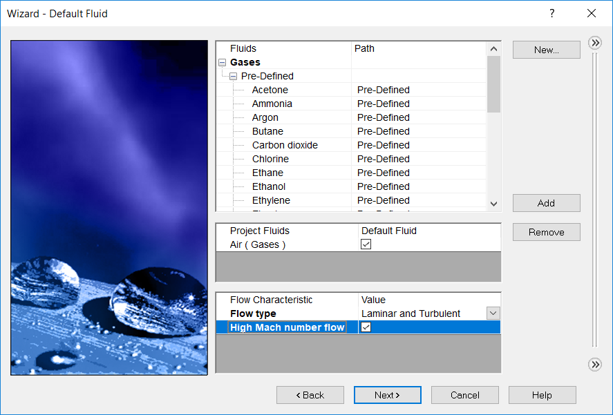
We must then specify the working medium. In this case we add air from the library of pre-defined fluids. We specify the flow to be of high Mach Number because we are expecting such a solution. Note that if this is not checked, the solver will work with a warning saying supersonic flow is detected and manual stop condition is recommended.
Set up working fluid.
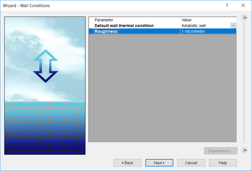
We define the wall to be adiabatic and with some roughness. These parameters are irrelevant to some extent to this simulation.
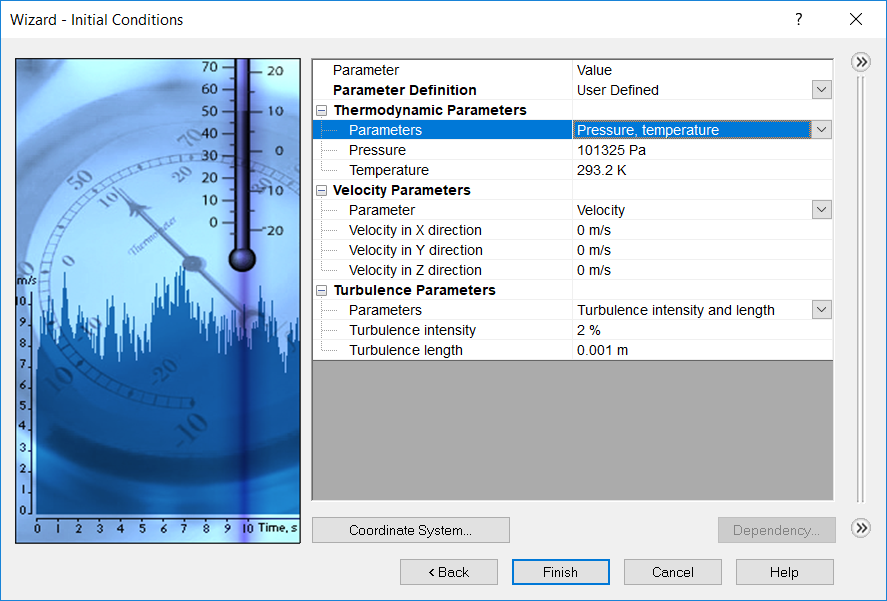
The initial conditions are set to ambient for the solver to start. If we can already anticipate the final solution to some extent, either by analytical reasoning or by previous CFD calculations, we can modify this initial condition for the solver to converge faster. This will be illustrated in the next part of this article. If we are continuing a previous calculation, previous results may be made use of, and SOLIDWORKS Flow Simulation makes such automatic provision, as we shall see in the solving process.
It should be noted that, however, that it is possible for a different solution to develop from the desired one if the initial conditions are not set up properly. In this case ambient static condition would work fine, because by physical reasoning, given the boundary conditions we will specify later (a supply pressure and a back pressure), the flow will develop into the supersonic jet even if it start from ambient (i.e. like the rocket engine not yet ignited), however, this may not always be the case. Alternatively, a poor set of initial conditions may yield no converging solution at all.
Initial conditions.
We have by now fully set up the simulation project. We now have to define two things:
The boundary conditions for the solver, as required universally by CFD
The “goals” as SOLIDWORKS call it. Goals are parameters that you desire to know (and in the solver’s default assumption, has to be made convergent) from the simulation. We can, however, relax the requirement that the goal has to be convergent when a goal is being set up. In this project we require all goals to be convergent.
A good discussion of convergence can be viewed here. Note that SOLIDWORKS Flow Simulation has an internal working mechanism that is fundamentally different from, say, ANSYS Fluent. We shall not go into depth here.
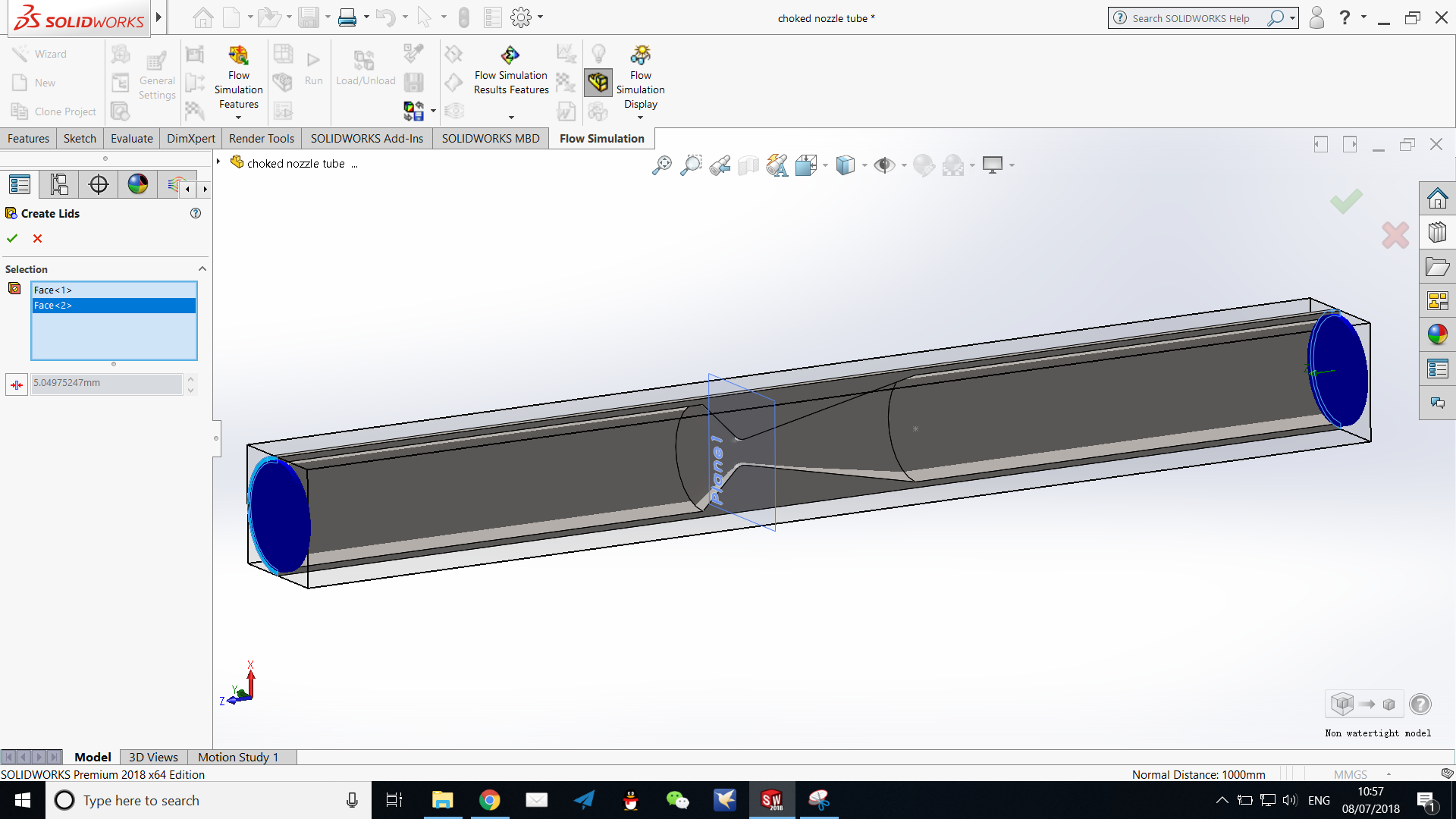
However, before that could be done, the computational domain must be defined. Recall that previously we have defined the simulation to be internal, so we must have a watertight internal chamber for the simulation to progress. In SOLIDWORKS this is conveniently achieved by using “lids”, i.e. automatically generated solid features sealing the openings of the model. We can create two lids at both ends of this tube to make our model watertight.
Using lids allows complicated models to be broken down and analysed separately. For example, the inlet manifold of an engine is connected to the inlet and the cylinders in reality, but if we seal these connections with lids we can analyse this part by itself and still obtain its flow characteristics, without having to solve for the entire model of the engine. It should be noted, however, that the boundary conditions applied to the lids must represent accurately the conditions that will be present when the part is connected to another, for example, it would be faulty to apply the same back pressure on all the cylinder connections of an inlet manifold, because at a certain instant only one cylinder would have an open valve, and, therefore, admitting air.
Sealing the model with lids.
I shall then define the two boundary conditions acting on the two lids respectively (note that since these lids are not present in reality, the real meaning of these surfaces I am here using are the respective spacial planes, and since that I have sufficiently long uniform sections upstream and downstream, the thickness of the lids does not have an effect):
Supply side, total pressure 5 MPa, temperature 1500K (modelling the outlet conditions of a combustion chamber)
Back pressure (environmental pressure) 20 kPa, temperature 220K (modelling atmospheric conditions at high altitude)
We can then create the goals we are interested in. In this case, I have required for the global Mach Numbers (max, min, avg, and bulk avg, just to make sure the entire flow field has reached steady state), and some properties at the exhaust plane of the tube (these are referred to as “surface goals”, also supported are global, point, and volume goals).
It is worth noting that SOLIDWORKS Flow Simulation also supports equation goals. In this case I have created an equation multiplying the exhaust mean velocity with mass flow rate so as to get an estimate of the gross thrust of the exhaust tube.
Creating a surface goal.
After goals are created, the model is ready for meshing and solving. SOLIDWORKS Flow Simulation can do the meshing automatically for the global mesh, and you have the option to add a local meshing. The property of the global mesh, however, are controlled by relatively few parameters and, therefore, may not have the same level of adaptability compared with the high-end CFD packages like ANSYS Fluent. In this project it may be worthwhile to add a local meshing around the choked nozzle, but this is omitted for solution speed.
The last step prior to solving is to set the calculation control options, mostly when shall the calculation stop, i.e. what is the convergence requirement in most cases. A basic user can leave these settings untouched and SOLIDWORKS would automatically define the stop conditions. It is, however, possible to modify these by hand, and this, at most of the times, would allow one to set up the calculation in accordance with the relative importance and the allowable unsteadiness of the goals. We would do this in the next post of this series.
In part 2, I would present the process of calculation control, running the solver and monitoring its process, and, finally, the ways to present the results, and their relative merits.