In 3D modelling, there are usually many different ways to complete the same part. For example, to model an axle-like part, there would be extrusion, extrude cutting, revolution, and other possible methods. Every design engineer has his own habit of modelling, but in the very same part, different modelling methods will yield completely distinct model structures, despite generating the same geometrical profile. This is illustrated by fundamental differences in the design tree. There will almost always be a certain structure of the design tree that would be preferable over the others for viewing, modifying, and interfacing with the model, but which structure would be preferable will again depend on the model itself and its intended use, without universal guidelines. The larger the scale of the engineering project is, the more clear, rigorous, and consistent the design engineer is required to understand and practise a certain method of modelling.
Therefore, design engineers are required to master a range of modelling methods with proficiency. This article aims to introduce a certain method, in which solid modelling is guided by the sequence of machining. This will be illustrated by the modelling of a shaft in SOLIDWORKS. 3D modelling software these days are more or less similar in functions and operation, and, therefore, the method introduced in this article is intended to be universally applicable. However, it should be noted that, under many circumstances, modelling as guided by machining sequence is not the optimised method, or will even be more complicated than other methods. However, employing this modelling method will help the design engineer greatly in clarifying the production process, which will be proven valuable when the technical requirements of a design are being compiled. Models generated by this method will also be better in terms of compatibility with CNC machines.

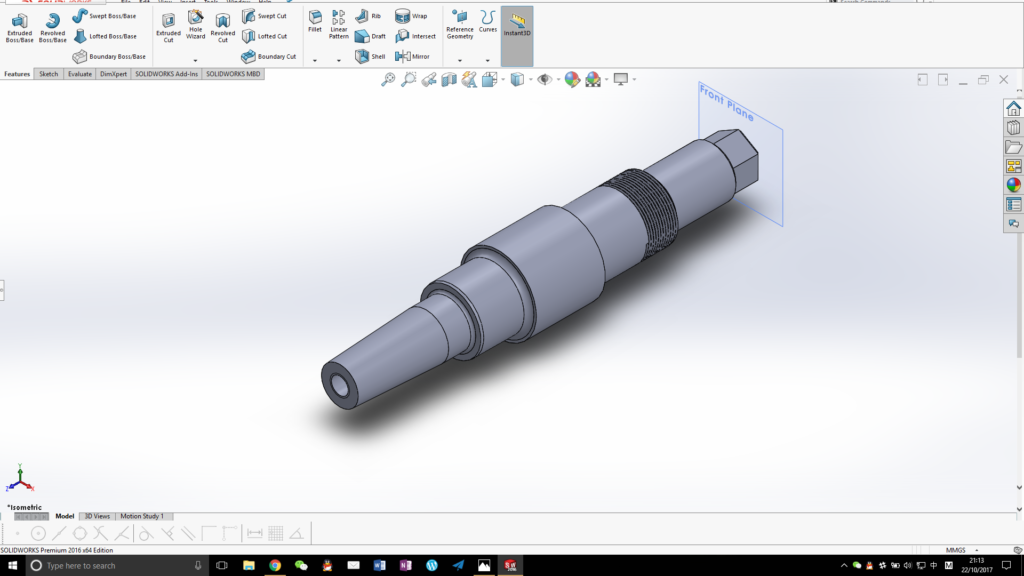
The shaft that the author will be modelling is as illustrated in Figure 1, and it is a stepped shaft supported by two bearings. One end of this shaft is tapered with a tapped hole, and the other end will need to be in hexagonal shape. At the end of one certain step, some thread will have to be made.
We can then very briefly analyse the production process of this shaft. Dimensional tolerance of this shaft is required to IT7 level, and, therefore, the principle machining process required would be chosen as turning, while the journals where the bearings will be fitted onto might need some grinding and polishing. For simplicity of the manufacturing process, the thread can be turned with a single point form tool, and the tapped hole can be drilled out on a lathe and then tapped with a machine tap. It is not possible to turn the hexagon on this shaft, and this will have to be milled, which can be the last process in this sequence.
Therefore, we can briefly list the machining process required to make this shaft in time sequence:
- Obtain material
- Face the material and centre drill
- Rough turn and finish the outer diameter (giving the largest OD of this shaft)
- Rough turn and finish the steps on the left, and turn fillets at the same time
- Try the bearing and do some hand polishing as required
- Turn the taper, drill and tap the hole, the left side is now finished
- Flip the part around, turn the steps and the fillets
- Turn the thread
- Try the bearing and polish as required, the right side is now finished
- Hold the part in a division head on a milling machine, and mill the hexagon
It should be pointed out that this sequence cannot represent the actual working process. Some machinists like roughing everything before giving the finish, while some like to finish one side before flipping, in order to guarantee high straightness and coaxiality. Some like polishing as they go, while some like leaving polishing to the very end. This article is not dictated to these technical details in machining, especially these questions do not have any significant influence on the model that we are going to make.
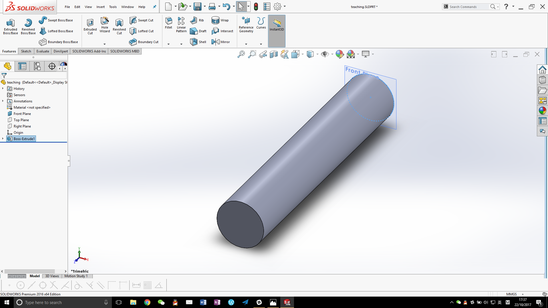
We now build the solid model following the sequence as listed above. First, we shall observe the first three steps, and it can be found that these three steps can be completed in one operation in SOLIDWORKS. This is because facing will not have to be included in the modelling, and the model does not normally include centre drills (one centre hole of this shaft will, later on, be drilled out into a tapped hole, so if we model the centre holes, some error will occur later on). The optimised modelling method would be to extrude a cylindrical boss, assigning the largest diameter of the shaft (31) when sketching, and assigning the total length (163) when extruding. Now step 1, 2, and 3 are completed.

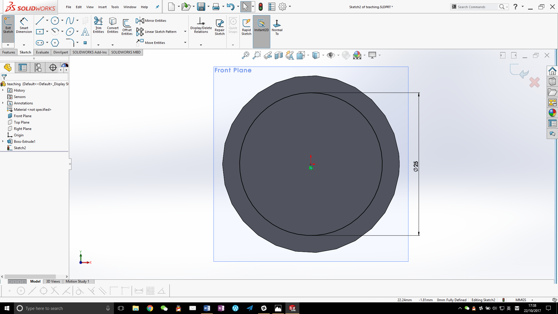
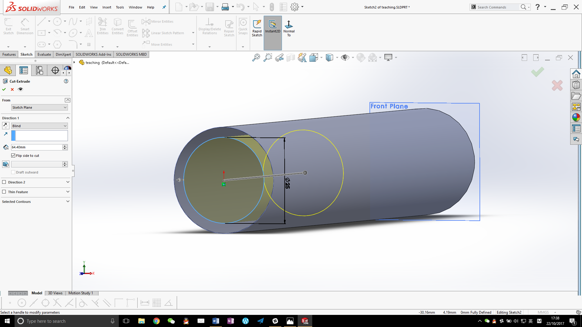
The following modelling will have to start from one side, and we shall start from the left for natural reading. The first step requires that a length of 64.4 from the left end of the workpiece be turned down to an OD of 25, and a fillet of radius 2 will be required. It should be clarified that, although this must be done in one operation when machining on a lathe (by form tools on a manual machine, or by CNC machine), one cannot do the same in SOLIDWORKS, but will have to divide this into two steps. We first use extrude cut command, make a sketch of a circle with diameter 25 on the left, and cut in the reverse direction with a depth of 64.4. A fillet of radius 2 can then be added with the fillet command.
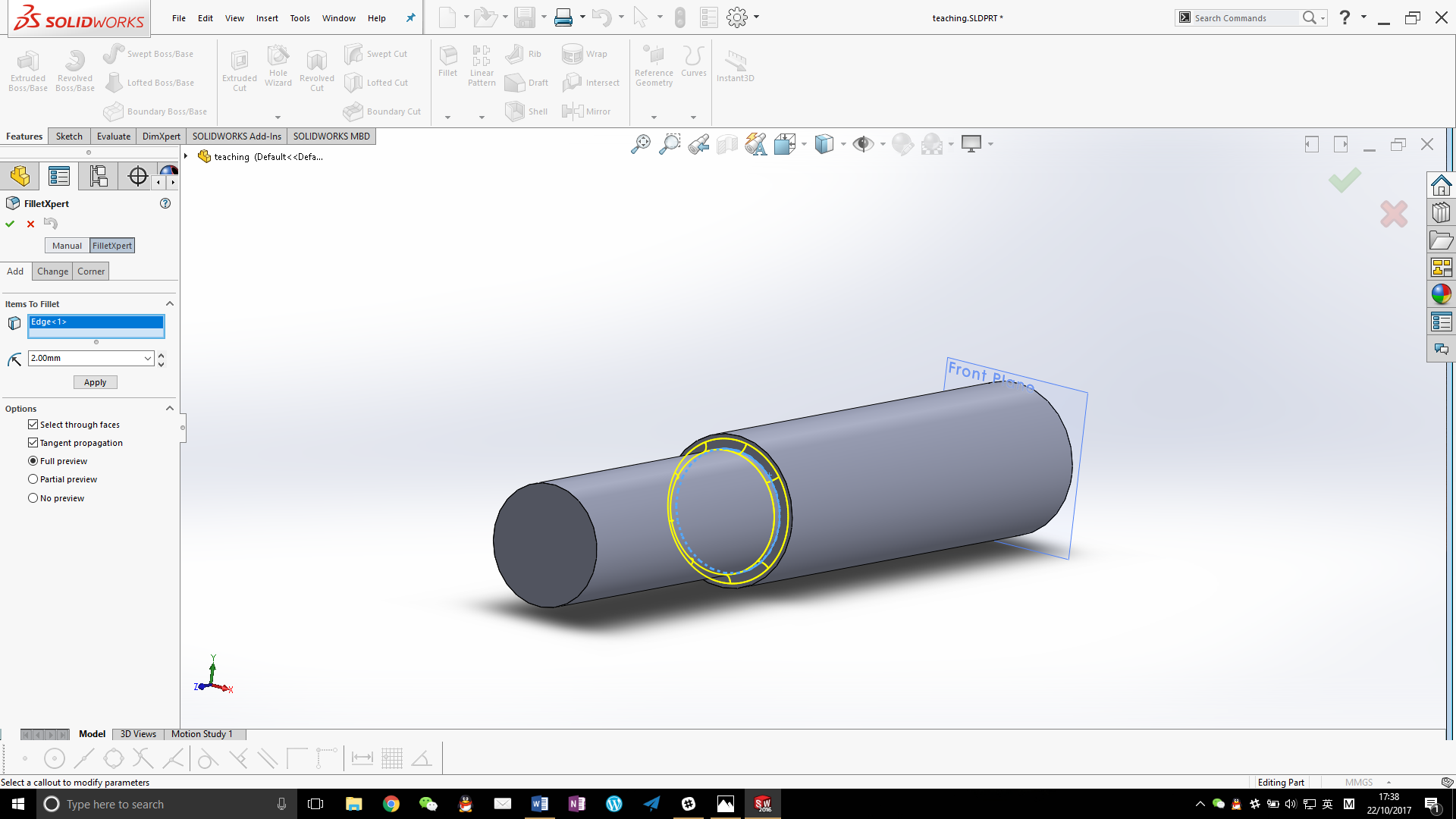
Reading the drawing carefully, and one can find that a chamfer with size 1*10deg is required on the end of this step, which is to help to assemble the bearing. This feature will have to wait until the edge is revealed after the making of the next step, regardless of in modelling or in machining.
The second step requires that a length of 45 from the left end of the workpiece be turned down to an OD of 18.5, and a fillet of radius 1 will be required. We first use extrude cut command, make a sketch of a circle with diameter 18.5 on the left, and cut in the reverse direction with a depth of 45. A fillet of radius 1 can then be added with the fillet command.

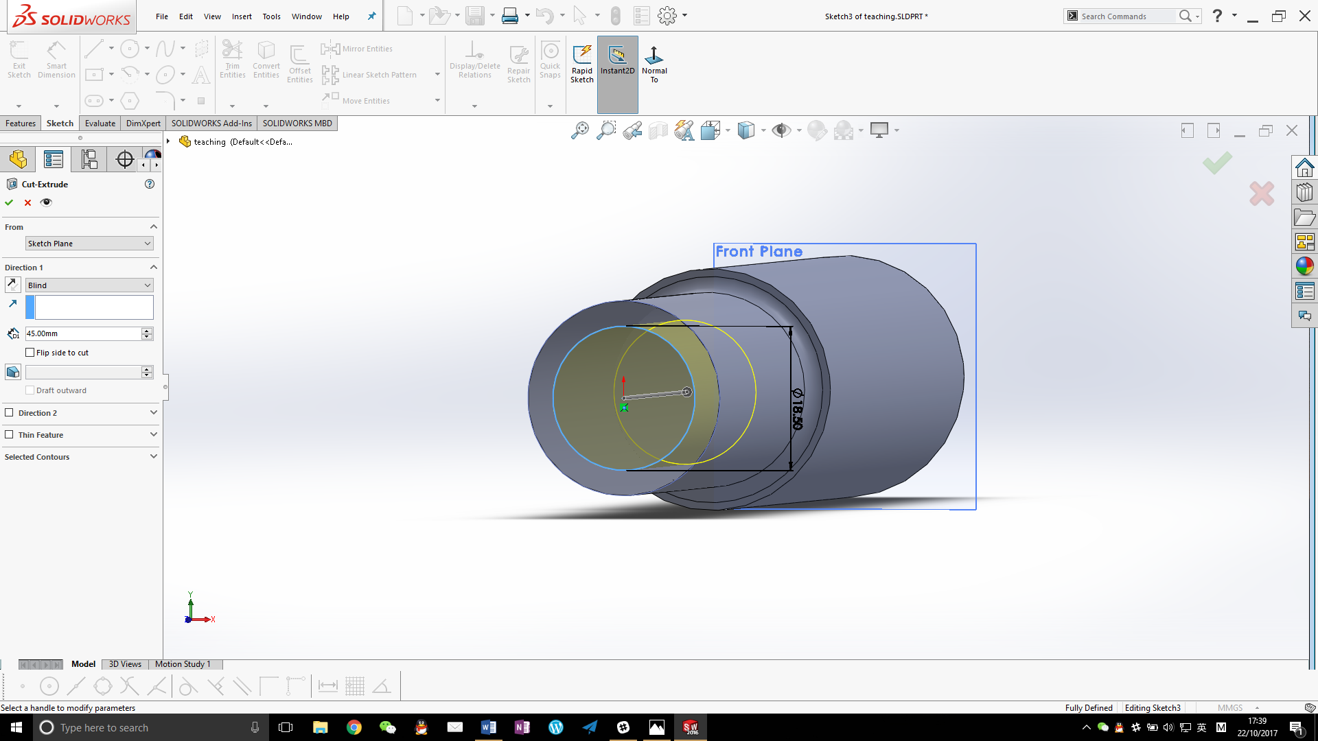

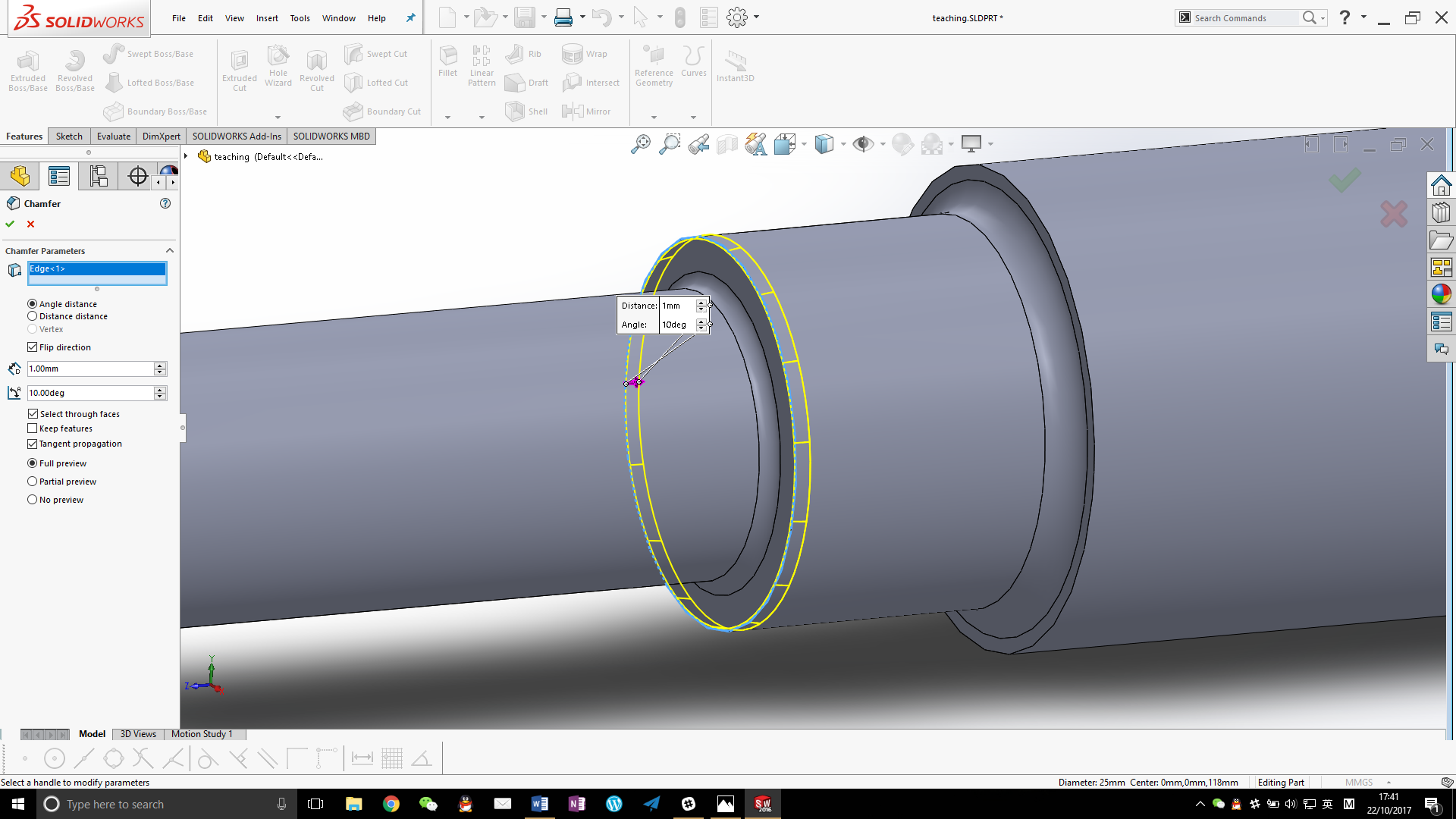
Now we are ready to add the 1*10deg chamfer, which can be readily constructed with the chamfer command. Due care should be taken to chamfer on the correct side, as this chamfer is not symmetrical. Previewing can be helpful in this case.
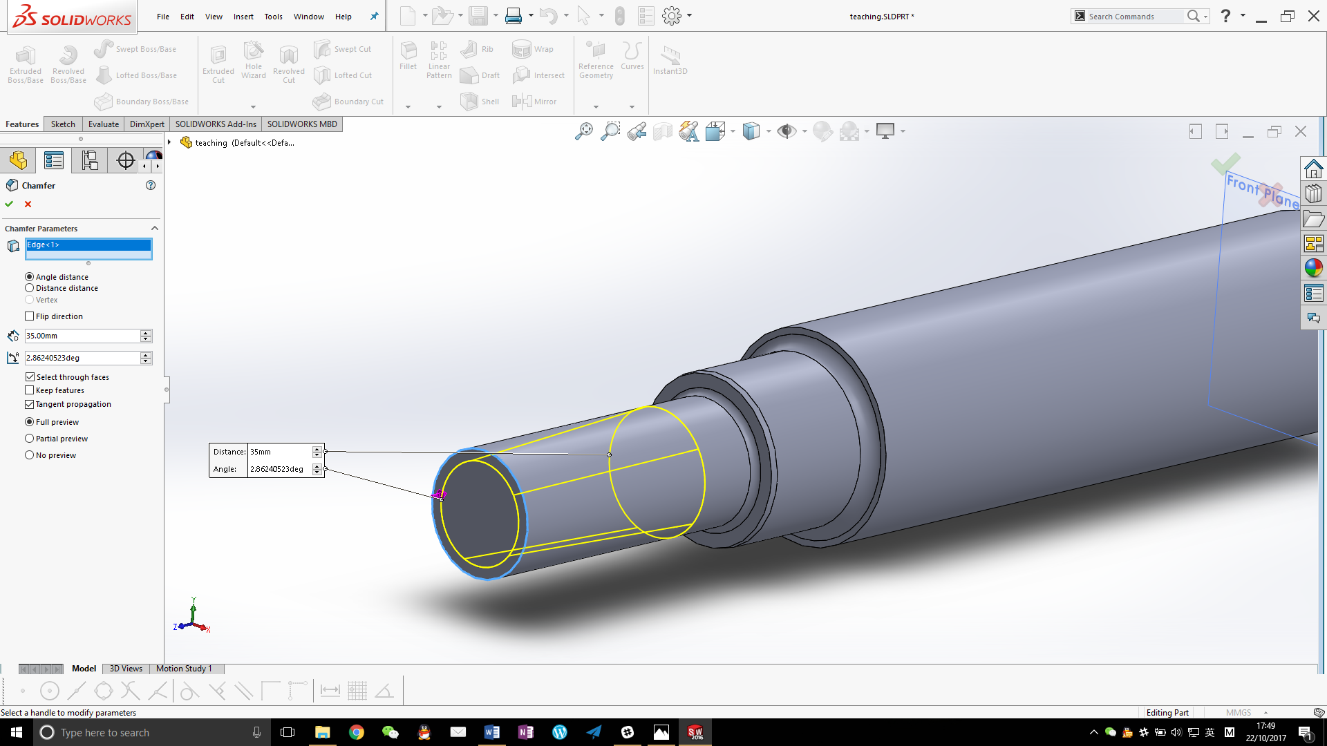
The taper may be constructed after the second step has been modelled. In the process of modelling, we shall use such method that represents the process of material removal best, and, therefore, a chamfer command can be ideal. Design engineers not using the method introduced in this article may choose to use the draft command to construct this taper, or to construct it by revolving a sketch. It should be noted that the angle of the chamfer concerned here should be computed by the built–in function of SOLIDWORKS atn(0.05)rad (proper units must be specified), instead of computed manually and entered, in order to guarantee precision in the internal computation of the software.
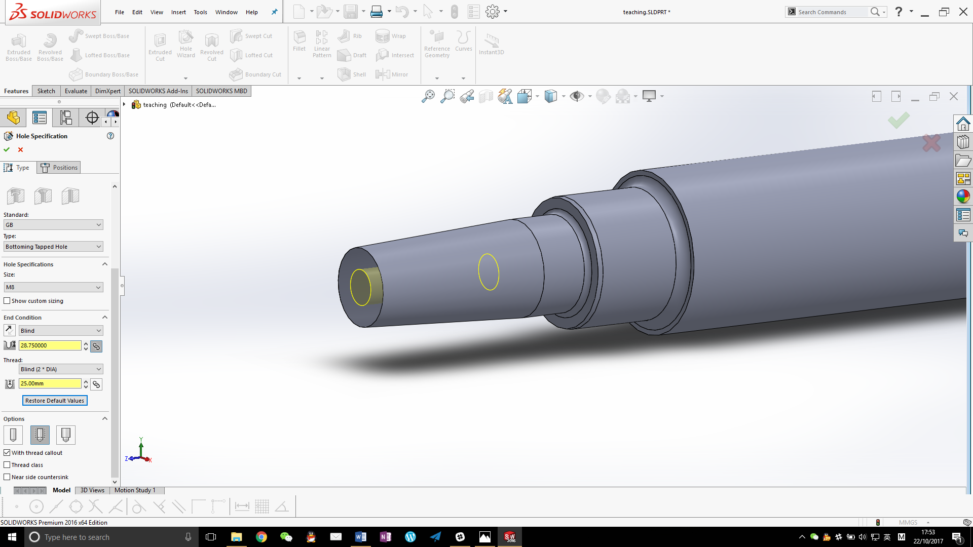
The tapped hole on the far left can be directly modelled by the hole wizard available in SOLIDWORKS, and the drill depth can be computed automatically after setting the tapping depth (the drill depth does not have much influence in actual design & manufacturing, at least not in this part. The machinist may choose to drill a bit further rather than shallower, if machining manually, since this depth is not very easy to control). The left side of this model is finished by now.
The first step on the right side requires that a length of 70.6 from the right end of the workpiece be turned down to an OD of 25, and a fillet of radius 2 will be required. We first use extrude cut command, make a sketch of a circle with diameter 25 on the right, and cut in the reverse direction with a depth of 70.6. A fillet of radius 2 can then be added with the fillet command.

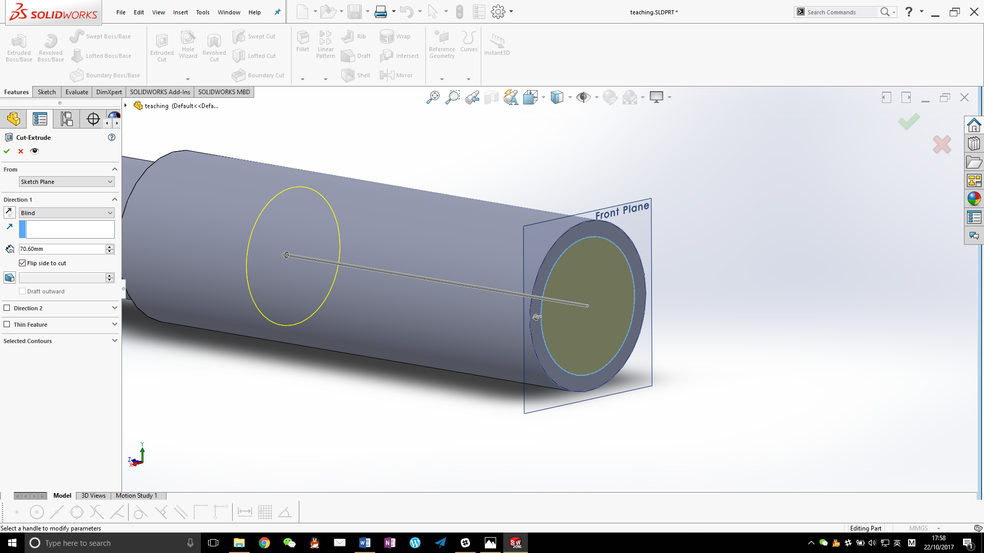
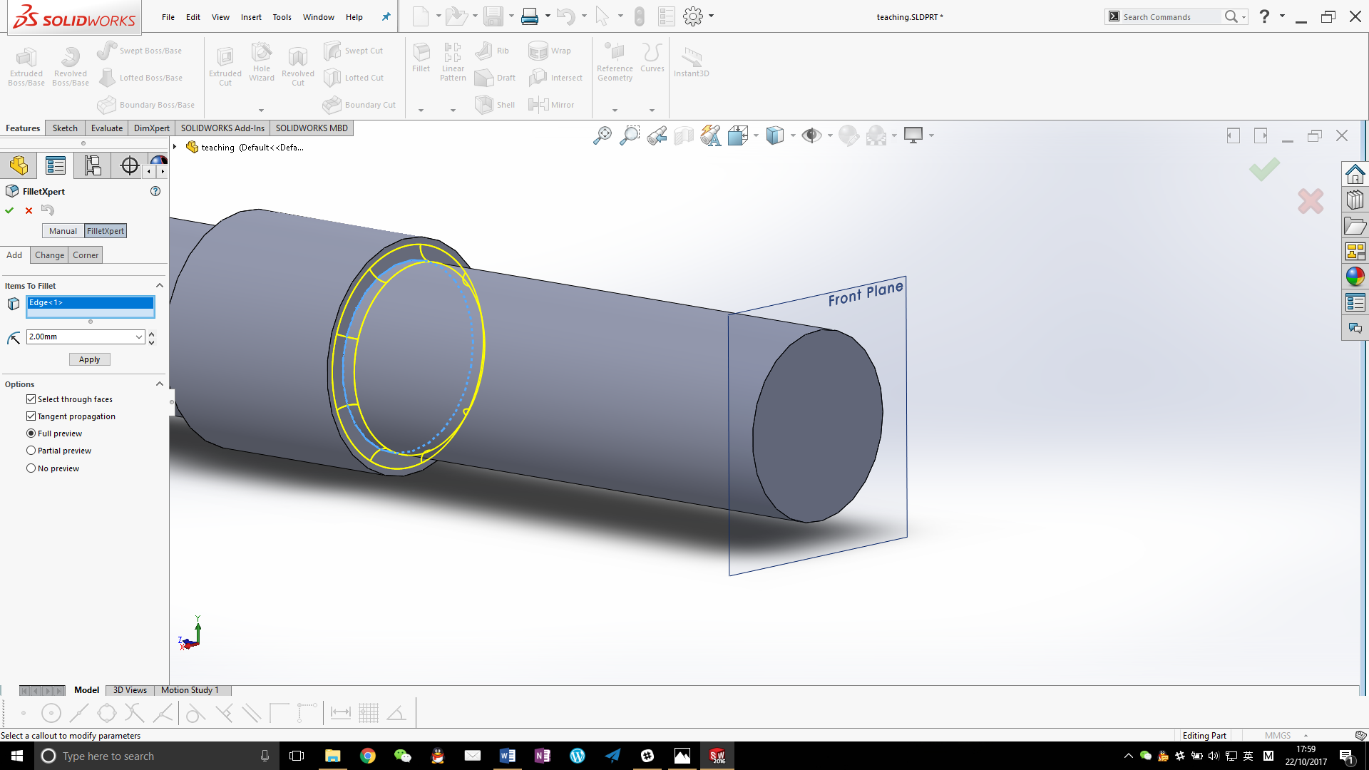
It should be noted that there shall be thread at the end of this step, which can be possibly introduced in SOLIDWORKS now, but usually this kind of thread is turned in actual manufacturing only after the next step has been machined and the edge revealed, so we do not model the thread at the moment being. Turning of the second step requires that a length of 38 from the right end of the workpiece be turned down to an OD of 20, and a fillet of radius 2 will be required. We first use extrude cut command, make a sketch of a circle with diameter 20 on the right, and cut in the reverse direction with a depth of 38. A fillet of radius 2 can then be added with the fillet command. These operations are highly repetitive, as it is in actual machining, so we shall not demonstrate it here.
The thread can be added after the last step has been modelled. In fact, we can choose not to model this thread in this model, and just add a representation to the final drawing to be produced. However, we can model real-view thread in SOLIDWORKS for the sake of visualisation. Please note here that, in order to achieve a better-looking start, the start of the thread has been offset, and the ‘keep thread length’ option chose, so that we do not need to make any compensation to the offset introduced. There is a mistake in the drawing of this part, and M15 should be changed to M25. Because M25*1.0 is not standard coarse pitch thread, the diameter and pitch of the thread need to be overridden.

The turning of this shaft shall now reach a conclusion, but there is still a hexagon shape to be milled, which can be conveniently modelled by extrude cut command, which represents the operation of milling well. It is observed that some chamfer has been drawn in the technical drawing of this shaft, with one of them not dimensioned. We can choose to use some approximate size for this kind of unclear instructions. In actual manufacture, these chamfers do not have any influence on the functionality of the part, and this design should be mainly out of the consideration of preventing injury due to sharp edges. Therefore, adding some chamfer manually by a file should suffice.
Readers may be confused that, the diameter of this hexagon shape is smaller than the diameter of the journal on which it is going to be machined, so why does the journal not needed to be turned to the correct diameter beforehand? This operation is possible but completely redundant. Milling this hexagon is a very basic manual machining process, during which the machinist will locate the edge of the workpiece (by a wobbler or some similar means) and zero his coordinates correspondingly, where is precisely a radius’ distance from the centre of the shaft. Every face of the hexagon is 8mm away from the centre, which is trivial to determine without the necessity of any knowledge of the circumcircle. This distance does not need to be changed again once set in the process.
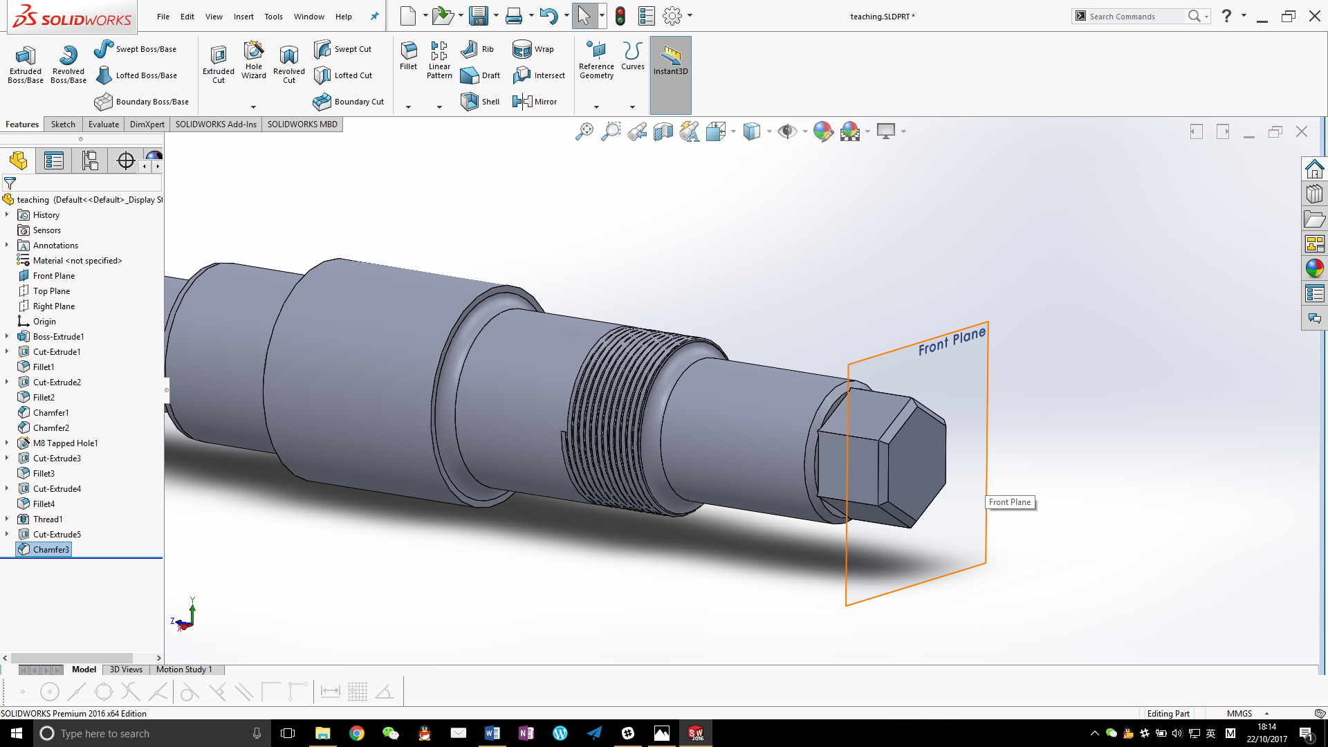
Now we have finished modelling this part, and certain housekeeping work shall be in order, like defining the material, which is not within the scope of our discussion.