This example is encountered by the author by accident during mechanical design, and it is considered as a precious illustrative instance of the “design for manufacturing” principle. Therefore, this article is written and the example shared with the readers. Should you have a different opinion on this instance, comments and discussion are welcomed. The author is still learning mechanical engineering, and, therefore, should this article contain errors, please point it out, thanks in advance.
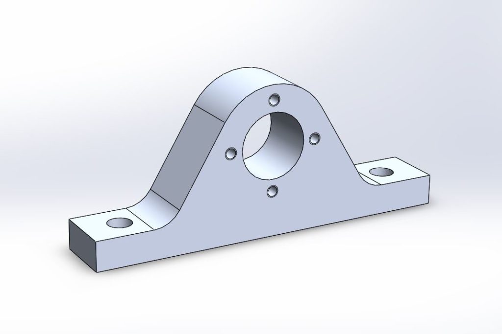
The part being designed is a bearing housing, the bore of which would house a flanged brass bush self-lubricating (contains graphite) sliding thrust bearing. Considering the geometrical relationship between the housing and its surrounding parts, the requirement of assembly and disassembly, and requirement of appearance, the part is designed to take the shape as illustrated in Figure 1. Only one of this housing needs to be made, and, considering that the workshop cannot make casts, it is decided that this part will be machined directly from metal plate.

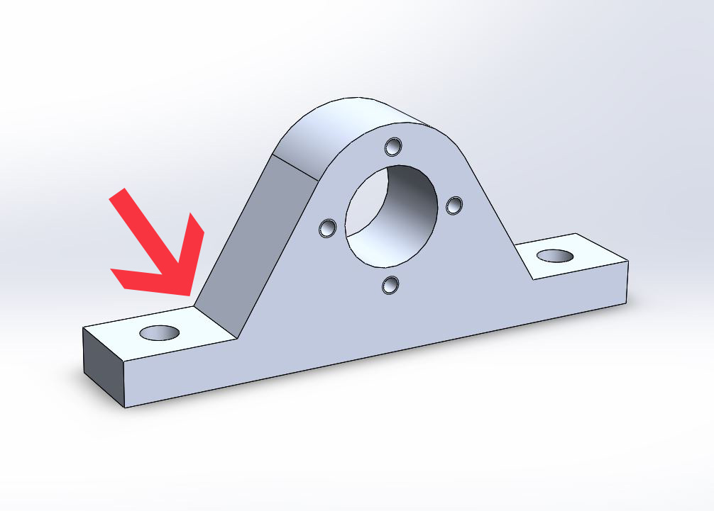
However, after due consideration, it is decided that a 10mm fillet has to be added at where the arrow points to in Figure 1. To introduce these fillets is for the purpose of simplifying manufacture. Generally, introducing fillets on workpieces will complicate the machining process, but how can these fillets do the contrary? The reason will be analysed below.
By traditional machining techniques, it is impossible to make sharp corners on profiles curving inwards. Let us take a turret milling machine for example, a turret mill uses a rotating tool to machine the workpiece, and, therefore, on the profile the tool passes, even though the feed suddenly changes direction, a fillet of the same radius as the tool will be left, and this is unavoidable on both manual and CNC turret mills. Therefore, in order to form a sharp corner like the one shown in Figure 1, one can either trim the fillet sharp in some way or use non-conventional manufacturing methods. The author believes that, in order to form the sharp corner, the following are feasible solutions:
- Get rid of the fillet by bench working techniques, or shave the fillet off by reciprocating machine tools (planing, etc.).
- EDM wire cut the raw material
- Cut the raw material by laser, plasma, or water jet.
Very obviously, method 1 needs one more process after CNC milling (profile of this part is unsuitable for manual machining), and the cost will be increased, which is not compliant with general design requirements. If a bench worker is to trim the fillet by hand, precision cannot be guaranteed, unless the bench worker is very experienced. Besides, if the fillet dimension is reduced out of the consideration to reduce the labour of the bench worker, then a smaller tool of reduced stiffness must be used during the milling process, and, therefore, precision of the entire part can be compromised. If reciprocating machine tools (high vibration) are to be used, not only precision cannot be guaranteed, but fixture and clocking problems will also arise, considering the part must be flipped over during the process.
Method 2 is non-conventional manufacturing, and it must be done in a workshop with such machinery. Wire cutting can also be very costly. Considering that the holes must be done on turret milling machines, inconvenience can be introduced by having to clock the workpiece in using the outer profile. On the contrary, if the fillet is added, the raw material can be clamped down onto the milling machine and finished in one go, both the profile and the holes. If absolute coordinates are to be used, it is likely that a high level of precision can be achieved.
The equipment needed for method 3, especially equipment with the capacity of cutting plates of a thickness of 25mm, is not easy to find. Although the cost of cutting is lower than method 2, but this will only be obvious in mass production (in which a bearing housing will be cast anyway). Furthermore, the surface finish of these methods are very bad and often tapered, and further machining will be required to reach the requirements. However, machining clearance is not easy to control with these methods. Same problem of clocking the workpiece will be introduced by this method.
To conclude, it is obvious that adding these two fillets can reduce the manufacturing process down to two steps (CNC milling, drilling bolt holes), which can be reduced into one if a machining centre is available. This is certainly very desirable and can significantly reduce the cost.
Why is a fillet with a radius of 10mm chosen? This is out of the consideration of accuracy in the machining process. Those who have used a turret milling machine must know, the larger the diameter of the tool, the better its stiffness, and, therefore, deflect less under the same amount of cutting force, which in turn improves the accuracy. 10mm is the largest that can be accommodated without interfering with the bolt heads in this part. Furthermore, adding large fillets reduce the concentration of stress, and the fatigue lifespan of the workpiece can be prolonged.
There has been people asking about the possibilities to machine the part vertically on a CNC turret milling machine, i. e. feed the cutter axially in order to create the sharp angles. I have not tried this, but I believe this is going to be problematic.
Firstly, a piece of raw material that is significantly larger than the part must be used, in order to hold the work piece securely in a vice for machining, and this will lead to waste. Any attempt to remove this excessive amount of material in one go will introduce huge cutting force in the machine and the work piece.
Secondly, the work piece will have to be rotated by 90 degrees before further features can be machined, and this will lead to the same problems as described in the article.
I am not arguing that making sharp angles is impossible, but adding fillets when such fillets will not interfere, but improve the functionality and quality of the part, and simplify the manufacture process, then this should definitely be considered by the designer.