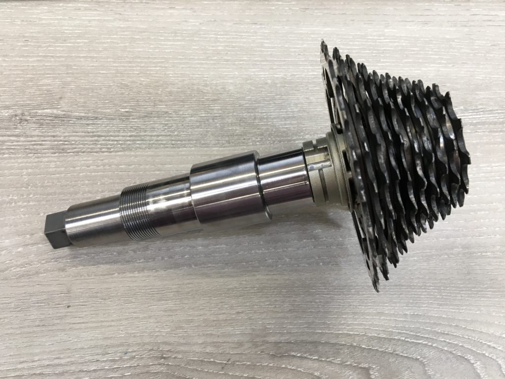
The author recently designed and constructed an aluminium collet, and problems have arisen in the design and installation. After the collet has been fitted to work correctly, experience has been summarised from this instance, and this article is written to share it with the readers.
Regular collets encountered in mechanical engineering are made out of steel, the most common one being ISO C45E4 medium carbon fine grade general purpose structural steel, out of which wide ranges of standard components are manufactured. However, the design discussed in this article is to connect specialised components, and, therefore, non-standard fastening methods have to be adopted. As to why the collet has to be aluminium, it is out of the consideration of protecting the inner surface of the hub (which is a specialised component this design has to use, made out of aluminium), and, therefore, it is required that the hardness of the collet shall not be excessively high, otherwise the hub will be badly scratched if slipping occurs. Even though aluminium has been chosen, serious and rapid wear has been observed since the collet entered service.
Using a collet to connect the shaft and the hub is the only reasonable solution left for the designer after analysing the construction of the hub. The shaft of this collet connection is to be designed for the purpose, and the design can be varied freely to suit the need. However, the hub is a bicycle component, the design of which does not have to consider the possibility for it to be fastened onto another machine rigidly, and, as a consequence, there is little space for modification for the purpose. The bore of the hub has multiple stages, some of them of coated surface finish and unknown dimension. The outer surface is coated, and has specialised splines, and, therefore, holes cannot be drilled onto it. Wall of the hub is so thin that machining a keyway is considered to be impossible. Furthermore, the two stages of the profile are not concentric, and great difficulties are introduced in the attempt to connect it to the shaft. Collet connection is considered to be the method that would require the least treatment on the hub.
In order to guarantee that the hub runs coaxially on the shaft, the author believes that the original way of working of the hub must be analysed, and the design made accordingly. When this hub is used on a bicycle, shaft runs through the bore of the hub, and deep groove ball bearings are installed between the shaft and the hub bore. Hence, should the hub be required to run true on the machine under consideration, the surface of the bore on which the outer race of the bearings was originally installed must run true. Because the bore of the hub is staged originally and unsuitable for collet connection, it has been machined into a smooth bore (the machinist is required to hold the hub in an independent jaw chuck, and clock the bearing race surface in). The collet then was designed accordingly.

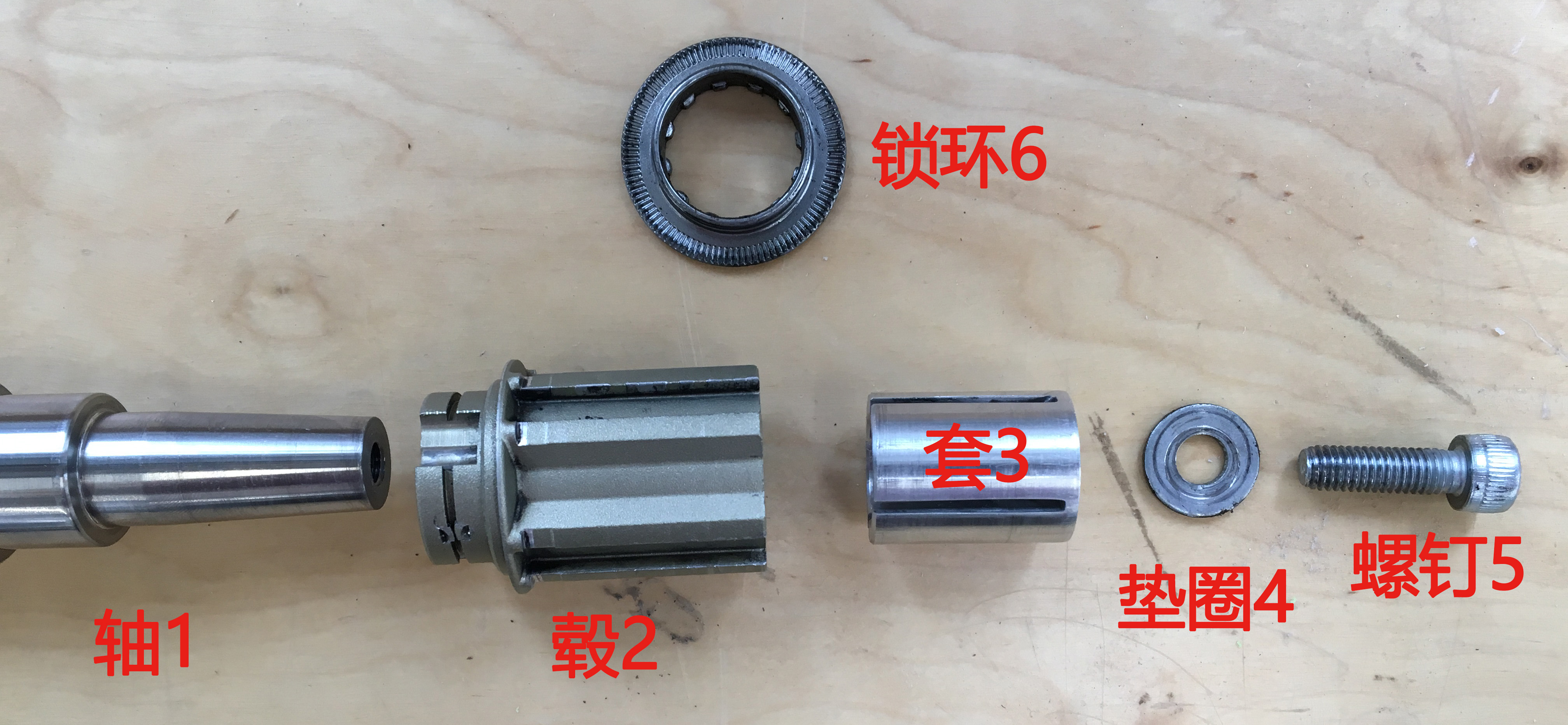
The architecture of the collet mechanism is illustrated in Figure 1. The connection is completed by the fitting of the tapered surfaces of shaft 1 and collet 3. Shaft 1 is the sprocket shaft, CNC turned to precision out of BS1407 silver steel, the taper of which is 1:10. Hub 2 is the hub that has been discussed, made out of unknown high strength aluminium alloy. Collet 3 is the design concerned, CNC turned to precision out of alloy 6082T6 round bars, and the slots cut manually. Washer 4 and screw 5 are standard fasteners, where screw 5 is made out of A4 stainless steel, grade 12.9, with a recommended torque of 40Nm.
When the system is assembled, hub 2 is pushed onto shaft 1, and located axially in one direction on a shoulder of the shaft. Then, collet 3 is inserted into the bore of the hub through its opening on the right, pushed lightly by hand until the tapers fit together. Screw 5 then goes through the washer and the hole on collet 3, and screwed into the threaded hole on shaft 1. Now if the screw is tightened, collet 3 is forced to move axially inwards, and expands radially as a result of the taper, gripping firmly onto the bore of the hub by friction, and the desired connection will be realised. This collet mechanism is required to transmit an operational torque of 100Nm, and the testing torque would be 120Nm, the criterion to pass being no sliding takes place. The benefit of such a design being, should different hubs be needed on the machine afterwards, which is likely, the only feature needed is a smooth bore of the correct diameter, without the need to process further for other features (keyways, etc.), which greatly facilitates the modification in the future.
Multiple problems have arisen in use, which are discussed below and experience has been drawn accordingly.
Lack of strength of aluminium alloy
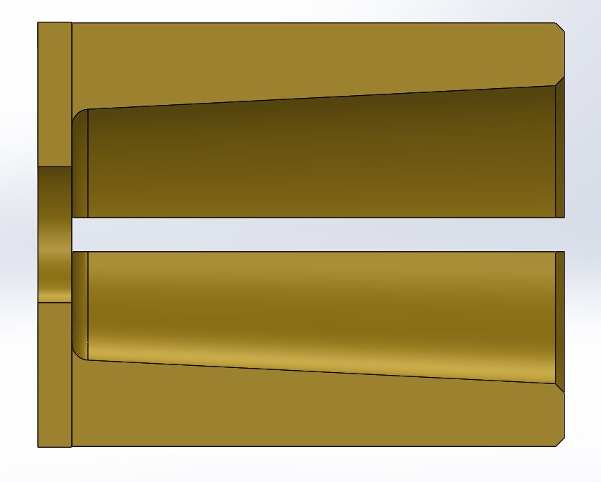
Due to the limitations of the architecture of the collet mechanism, axial load has to be taken solely by the closed terminal of the collet (see Figure 2, section view of the collet). It is discovered in assembly that, as a result of the lack of strength due to limited thickness of the closed terminal (2mm in thickness, limited by the lock ring used to secure sprockets, so the collet shall remain below the thread), when the screw is tightened, the terminal yields and deforms plastically under the act of a concentrated large axial force, which is, as a consequence, not transmitted properly. This is realised when the transmitted torque of the collet does not increase despite the screw has been tightened further, and the damage to the collet is revealed after disassembly. This is because the aluminium alloy used in this design does not possess sufficient strength to bear such load under the given structure, and the best solution would be to use a different material. As a temporary measure, it is required that a wide washer shall be used with the screw, and no further yielding is observed afterwards.

It is now planned to change the material into titanium alloy, which has considerable strength but a low elastic modulus that is similar to aluminium alloy, so it has the potential to be the ideal elastic material for the collet. No effort has been made to investigate this idea further due to the high cost expected by doing so.
Plastic deformation of the collet
When this collet mechanism is first installed, some radial play exists between the collet & the cap. When it is disassembled, however, it is observed that the play has vanished, leading to considerable difficulty of removing the collet, which was later accomplished by hammering. Analysis shows that as a result of the low yield stress of aluminium alloy, some plastic deformation has occurred after the first installation. The length of the collet has shrunk, while the wings have thickened, being crushed into such shape axially. Radial clearance has disappeared, as a consequence. The reduction of radial clearance is beneficial to the functionality of the collet, but this plastic deformation leads to problems 3 & 4. After due adjustment, no further plastic deformation is observed in the subsequent several installations. The author believes that this is a joint effect of the work hardening of aluminium alloy, and the redistribution of stress after the collet fits its space properly. This plastic deforming property can compensate for the improper fitting due to machining error, and can be of benefit if utilised well. However, design errors like those presented in problems 3 & 4 must be avoided.
Insufficient space between the collet and the shaft
When this collet is being designed, a 2mm axial clearance has been implemented between ends of the collet and the shaft. The actual clearance observed after the parts have been made is slightly smaller than this value. This clearance should not normally be this small, but the author thought the contact surface should be made as large as possible by increasing length of the shaft, so as to reduce normal stress, and avoid any damage to the hub. However, after the yielding discussed in problems 1 & 2 took place, this clearance disappeared, and the collet can no longer function. In order to correct this, the length of the shaft has been reduced by 2mm on a lathe, and the collet is observed to work as it should. In an improved design, the initial clearance is 4mm, learning from this experience.
Collision between the collet and the hub bore
The bore of the hub being used for this design still has a stage after being machined, and collision between this stage & the collet happened before the tapers fit correctly upon initial assembly. In order to resolve this issue, the collet is cut short by 2mm on a lathe.
Summary
The following several points are to be learned from the design & fitting process described above:
- Force flow within a component has to be designed reasonably, and stress analysis or finite element analysis should be conducted when necessary. Designs like the end of the collet, where a large force is transmitted by the bending & shearing of thin plates, should be avoided.
- The material should be selected with great care.
- When collets are being designed, radial tolerance should be controlled tightly, and high accuracy is to be required. For example, the taper of this design is 1:10, and if a play of 0.1mm exists between the collet & the hub, then the collet must advance by 1mm before fastening start to take place, and unforeseeable problems may occur as a result. Intermediate fitting should be designed radially (although clearance is not desired, an interference fit will introduce difficulties upon assembly & disassembly).
- Sufficient axial clearance should be left, and both ends of the collet should be considered to need to move in both directions. One direction is the required movement for the collet to expand, but radial error will introduce displacement in either direction.